

Home | Contact Us | Submit Troubleshooting Info | Search | Help
Output | Software Solutions | Proofing | Color, Screening and Calibration | Scanning | Digital Photography | Consumables | POS
Home | Contact Us | Submit Troubleshooting Info | Search | Help
Output | Software Solutions | Proofing | Color, Screening and Calibration | Scanning | Digital Photography | Consumables | POS
Lotem 400
If too much pressure is exerted on a plate by the Plate Loading Motor Wheel,
the plate may be dented. The excess pressure also prevents the loading of thicker
plates. If the pressure exerted is not identical on the right and left sides
of the Plate Loading Motor Wheel, registration problems may occur
This procedure describes how to adjust the Plate Loading Motor to prevent these
problems.
Adjusting the Plate Loading Motor Wheel
- From the GUI, open the front door of the machine.
- Remove the left and right Light Covers by removing the 2 screws holding them on each side.
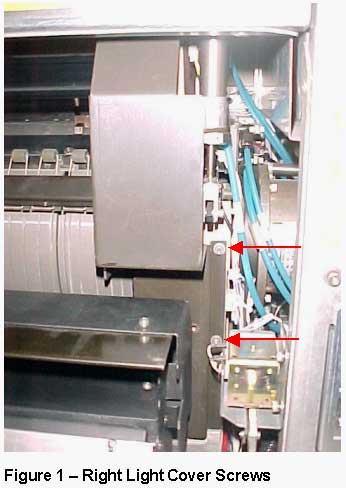
- Remove the Protection Cover Assembly by removing the 3 screws on the top, and the left- and right-side screws.
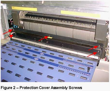
- Remove the Brush by removing the 4 screws.
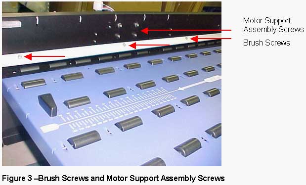
- Loosen the 4 screws on the Motor Support Assembly that hold the Plate Driver Motor. (See Figure 3.)
- Move the Plate Driver Motor Rubber Wheel down until it pushes against the two Rollers under it evenly.
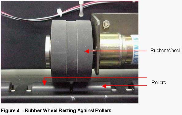
- Adjust the pressure so that a plate of 0.15 mm thickness can be inserted and released from between the Rubber Wheel and the Rollers without being dented.
Note: When you push the plate between the Rubber Wheel and the Rollers, it should cause the Rubber Wheel to turn smoothly.
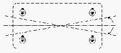
- When the pressure is adjusted, tighten 2 of the 4 screws.
Testing the Adjustment
- Cut a small piece of a 0.15 plate, about 10x1", and punch a hole in it.
- Attach the plate cutting to a weight scale.
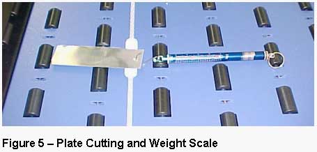
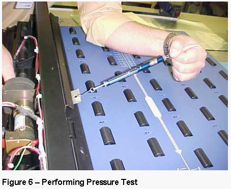
- From the GUI, turn on the Plate Driver Motor to speed four.
- Test the pressure on both sides of the Rubber Wheel. The pressure should be even on both sides, about 1 Kg. Even pressure on both sides verifies that the Rubber Wheel is straight.
If the pressure is not even on both sides, repeat steps 6-8, above.
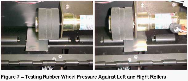
- Repeat the test procedure on a plate of 0.3 mm thickness.
- When the tests are successful, tighten the remaining 2 screws on the Motor Support Assembly. (See Figure 3.)
Note: From this point, to check loading and attachment, refer to Attachment of Plate to Head Pins.- If all tests are successful, install the Brush and secure the 4 screws, making sure the brush does not press against the plate. (See Figure 3.)
- Install the Protection Cover Assembly and secure the 5 screws. (See Figure 2.)
- Install the left and right Light Covers and secure the 2 screws on each side.
(See Figure 1).- Close the front door of the machine.