Applies to |
|
- Lotem® 800
- Lotem 400
- Lotem XL
- Lotem 400 Xpose
- ThermoFlex Mid/Narrow
|
Priority: Next failure
Release date: 10 May 2005
Document: 719-00494A Rev A
|
Problem |
|
The existing optic house opening (where the resolution mechanism fork
enters the optic head), is too large. Dust can easily enter through this
opening and damage the laser optics, resulting in reduced image quality.
|
Solution |
|
Prevent dust from reaching the laser optics by sealing the opening where
the resolution mechanism fork enters the optic house.
|
Time needed to
implement |
|
1 day (to include the readjustment of the fiber head for good quality
images).
|
Parts needed |
|
|
Part name
|
Quantity
|
Part number
|
|
Resolution cover
|
1
|
252-01715A
|
| Washer 0.8 |
2 |
252-01714A |
| Spring |
2 |
252-08569A |
| Resolution holder II |
1 |
252-08828A |
| Comp. spring |
1 |
318-00036 |
| O-ring |
1 |
316-00033 |
| FCO Updater Utility (diskette) |
1 |
651-00353A |
FCO document:
Sealing the optic house opening |
1 |
719-00494A Rev A |
|
Special Tools needed |
|
Loctite 242
Cotton swabs
|
Procedure |
|
The procedures for sealing the optic house opening comprise of three
steps:
Note: Before beginning
the procedure, expose a reference plate and put it to one side. After
completing the procedure, you will expose a further reference plate and
compare it with this plate.
Cleaning the optical V-groove assembly
Refer to the clean
the optical V-groove assembly document and complete the following
procedural steps of the document:
- Tightening the Lens, steps 1-10 (inclusive)
- Reassembling the lens and testing, steps 1-5 (inclusive)
Disconnecting the old resolution assembly
After cleaning the optical V-groove assembly, the second step
involves disconnecting the old resolution assembly:
- Move the carriage to 500 mm.
- Open the platesetter's rear door via Lotem Controller.
- Remove the rear upper panel and take out the unload tray.
- Shut down the platesetter via Lotem Controller.
- Disconnect the power cable, the detector cables and the ground cable
from the motor resolution:
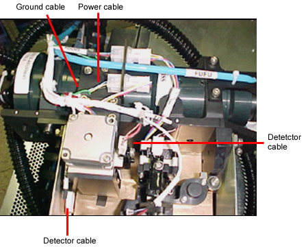
- Undo the four resolution motor screws with a #8-32" hex key
and remove the motor:

- Undo the two bracket connector screws with a #6-32" hex key and remove
the bracket:
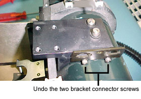
- On the holder resolution assembly, undo the shoulder screw with an
#4-40 L-hex key and undo the second screw with a #8 hex key. Remove
the holder resolution assembly:

- Disconnect the two springs attached to the fork:
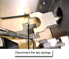
- Using a straight head screwdriver, undo the fork screw and then remove
the fork from the optic house:
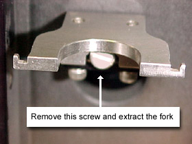
Constructing and connecting the new resolution
assembly
- Lightly dip a cotton swab in acetone and gently clean the optic house
opening:

Important: Do not insert
the cotton swab into the optic house.
- Make sure the optic house and all the FCO parts are clean and free
of dust.
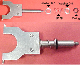
- Place the following new parts onto the stem of the fork assembly:
- Washer 0.8 (part no. 252-01714A)
- Comp. spring (part no. 318-00036)
- Washer 0.8 (part no. 252-01714A)
- O-ring (part no. 316-00036)
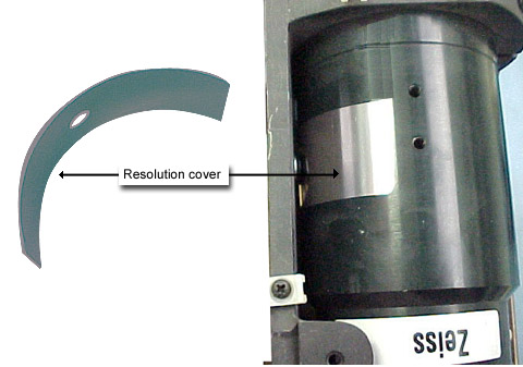
- Place the new resolution cover (part no. 252-01715A) over the optic
house opening (where the resolution mechanism fork enters the optic
head):
- Put Loktite 242 on the end of the fork and then insert the fork through
the hole of the resolution cover and into the optic head. Tighten the
fork screw with a straight head screwdriver. Make sure the fork can
freely move up and down.
- Reattach the two springs to the new fork.
- Place the new resolution holder (part no. 252-01715A) onto the optic
head:

Attach the resolution holder to the optic head with a shoulder screw
and a #8 screw. Once again, make sure the fork can freely move up
and down. If the fork's movement is not smooth, undo the resolution
holder and reattach it.
- Using a #6-32" hex key, reattach the bracket connector with two
screws.
- Using a #8-32" hex key, reattach the resolution motor with four
screws.
- Reconnect the power cable, the detector cables and the ground cable
to the motor resolution.
- Reinstall the unload tray.
- Reinstall the rear upper panel.
- Close the rear door.
|
When done |
|
- Start up the platesetter via Lotem Controller.
- Recallibrate the head: Perform focus test, elevation, resolution, intensity and delay.
- Expose a reference plate and compare the image quality to an earlier
reference plate.
|
Logistics |
|
Approved quantities:
|
CSC
|
Quantity
|
|
CAM: |
20 kits (5 per month)
|
|
CEU: |
10 kits
|
|
CAP: |
3 kits
|
|
CJP: |
5 kits
|
|
CMA: |
10 kits
|
|
Other: |
|
|
No Limit: |
|
Schedule supplies for first lots:
|
CSC
|
Week 40
(29/09)
|
Week 41
(07/10) |
Total
|
|
CAM:
|
10
|
10
|
20 |
|
CEU:
|
5
|
5
|
10 |
|
CAP:
|
3
|
|
3 |
|
CJP:
|
3
|
2
|
5 |
|
CMA:
|
5
|
5
|
10 |
|
Other:
|
|
|
|
Lead Time: 1 month |
See also |
|
Cleaning the Optical
V-groove Assembly procedures
|
|
Technical
contact |
|
Yaron
Shifman
Product Support Manager: Yaron Sofer
|
Date submitted |
|
16 Nov 2003 |

