Background |
|
When removing the Lotem's filter, the
lens, which is inside the head/lens casing, stays attached to the filter
and is also removed. When this happens, it is necessary to disassemble the
head/lens assembly in order to tighten the lens. To do this, open the back
of the head/lens casing, and remove the laser head to gain access to the
lens; then poke a long, custom-designed jig inside the casing and tighten
the lens. Creo Israel would like to extend its appreciation to Mr. Paul
Gallimore of Creo England for his help in preparing this procedure. |
Procedure |
|
Implement this procedure on rare occasions
(for example, to remove an overly tightened lens filter). This
procedure includes the following steps:
Overview
Figure 1, shown below, provides an at-a-glance, six-step overview of
the lens tightening procedure. Basically, all you need to do is remove
everything from the head/lens casing, insert the jig into the casing, then
tighten the lens. The entire procedure is detailed in Tightening the
lens.
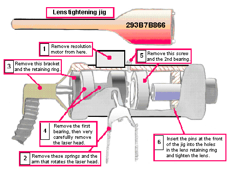
Figure 1
Tightening the Lens
- Open the rear door of the Lotem; then remove both the unloading tray
and the top back cover.
- Insert a cheater; then, using the carriage motor menu, move the
carriage to a position where you can work comfortably on the head (for
example, position 700).
- Shut down and power-off the Lotem.
- Remove the four screws at the top back of the head assembly on the
resolution motor; then remove the two detector connectors and the
motor power connector, as shown in Figure 2.
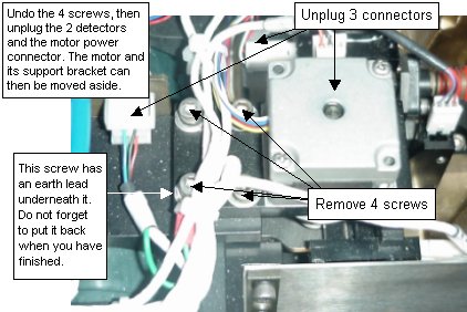
Figure 2
With the motor and mounting bracket
released, unhook the two springs underneath the motor that provide tension
to the
head rotation arm. The arm and springs are shown in Figure
1.
Note: When removing the motor and springs, mentally note how to reassemble them.
Pay close attention to how the resolution motor meshes
with the head rotation arm. This must be reassembled properly.
- Set the resolution motor aside; then, using a screwdriver, remove
the head rotation arm from where it protrudes from the head/lens assembly
casing, as shown in Figure 1.
- Remove the locking screw from the head/lens assembly
casing, and put the screw to one side:
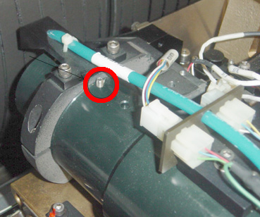
- At the back of the head/lens assembly casing,
cut and remove the various cable wraps that secure the black plastic
tubing in place, as shown in Figure 3.
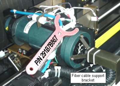
Figure 3
Note: Before removing the cable
ties, pay attention to how they are threaded through the two brackets. You
will need to put them back in the same way.
Important: From this point on in the
procedure, the fibers are unsupported. You must be very careful with them.
- Remove the screws from the fiber cable support bracket (Figure
3) and set the cable support bracket aside.
- From the back of the head/lens casing, remove
the black retaining ring, using the optic head outer key (P/N 291B7B867),
as shown in Figure 4.
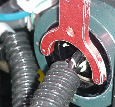
Figure 4
Note: You may need to temporarily
position the head rotation arm back through the casing so that you can
hold it to prevent rotation as you unscrew. There is a large spring washer
directly behind the retaining ring, which will fall out when you remove the retaining
ring. Remember to put it back at the end of the procedure.
- With the head/lens casing retaining ring set to one set, remove the
bearing behind it (see Figure 1); then carefully
pull out the laser head. When it is out of the casing, lay the laser
head over the V-block, as shown in Figure 5.
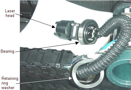
Figure 5
Note: If
you look at the end of the laser head (above), you can see where the fibers terminate.
This picture also shows the bearing, which is removed
during the next stage of the procedure, and the spring washer, which was
removed together with the retaining ring in step 9.
Both the bearing and washer appear in this picture only to show you what
they look like. At this stage in the actual procedure, they will have
already been removed.
- Hold the laser head in one hand; then, using the other hand, wipe
the front, shiny V-groove (holding the edge of the fibers) with a cotton
tip soaked in acetone, as shown in Figure 6.
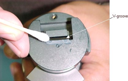
Figure 6
Note: Wipe the V-groove with the
soaked cotton tip in one direction only; then throw the
cotton tip away and use
a new one.
- From the top of the casing, remove the screw that reaches down into
the casing, preventing the immediate removal of the second bearing.
Note: To see how this screw causes an obstruction,
refer back to Figure 1; then look into the head/lens
casing.
- When you have removed the screw, reach a finger into the casing (if
your fingers are long enough) and pull the bearing out. You may need
to hook the bearing out with an Allan® key. If you use an
Allan® key, be very careful, because just beyond the bearing
is the lens (see Figure 1).
- Look into the casing to see the lens and the pinholes in which the
jig fits. Very carefully insert the optic head inner key
(P/N 293B7B866) into the head/lens casing, and fit the jig pins into
the holes on either side of the lens (see Figure 1).
Rotate the jig clockwise to ensure that the lens is securely tightened.
Reassembling the lens and testing
- Replace the bearing.
- Tighten the screw back down into the casing.
- Place the laser head very carefully back into position, and orientate
it so that the rotation arm can be passed through the head/lens casing
and screwed into it.
- Replace the spring washer and the retaining ring. The retaining ring
protrudes slightly, as shown in Figure 1.
Note: Do not overly tighten the retaining ring: it
will cause an unsmooth resolution rotation.
- Replace the fiber/tubing support bracket. Use cable wraps to secure
the black tubing to the bracket, as described in step
7 of the lens tightening procedure.
- Screw the rotation arm back into the head assembly by first passing
it through the head/lens casing; then hook the two springs back onto
the rotation arm.
- Re-insert the locking screw removed in step 6.
- Replace the resolution motor assembly by screwing the motor block
into place. Ensure that it connects properly to the head rotation arm.
Note: Remember to place the exposed earth wire under
one of the motor fixing screws.
- Put the detector and motor power connectors back in place.
- Check whether the resolution motor moves freely. To do this, power
on the Lotem and launch the application. From the Resolution Motor
menu, move the motor back and forth a few times between the home position
(HP) and the max pos app value (found
under the Properties tab of the Resolution Motor menu).
- Check whether the focus motor moves freely. From the Focus Motor
menu, move the motor back and forth a few times between the HP
and the max pos app value. To find the max
pos app value, select hardware>database>focus
motor; then
double-click the res 60 option.
Note: If both motors are not moving freely, find out
why.
- Fully calibrate the Lotem, including focus, intensity,
resolution, delay and elevation.
|

