Applies to
|
|
Lotem® 800 VL
FCO Kit number: 512-02635
Machine S/N:
Estimated implementation time: 2 hours
Logistics: See Action
required.
|
Type of change: Conditional
Reason: To curtail repeated problems with
pressure marks that are caused by the unload rollers.
Description: Replaces the standard unload roller
assembly with an unload roller assembly that includes a single
roller. |
Procedure
|
|
This procedure includes the following steps:
- Removing the currently installed unload roller
assembly
- Assembling the single-roller unload roller assembly
- Installing the unload roller assembly
- Testing unload roller function
Removing and disassembling the currently
installed unload roller assembly
- Release the cassette and remove it from the machine.
- Open the front door, right side door, left side door, and the rear
door.
- From the PC Controller, close the Lotem application.
- Shut down the machine and disconnect it from the main power supply.
- Close the air supply valve on the wall air pressure unit.
- From the front of the machine, remove
the unload roller piston.
- From the rear of the machine, disconnect the following:
Note: Cut and remove plastic ties, as required.
- Two side-to-side detector connectors, one each on the right and
left of the unload roller base.
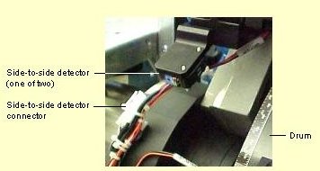
-
Unload gripper enable detector:
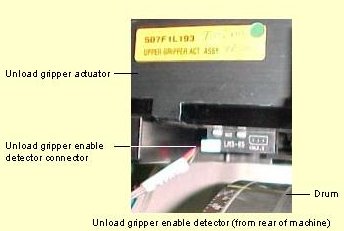
-
Unload gripper HP and end position (EP) detector:
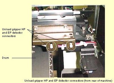
-
Unload roller HP and EP detector.
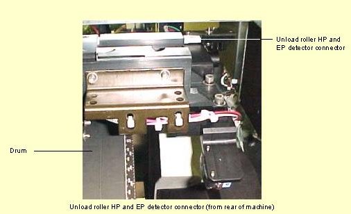
- Detach the blue air tubes from the unload gripper piston:

- From the front of the machine, remove the eight screws (four on each
side) that secure the unload roller assembly base to the Optomec.
Note: The unload gripper/roller assembly is mounted
on pins.
- From the rear of the machine, carefully lift the unload gripper/roller
assembly off of the mounting pins and remove it from the machine.
- Remove the
unload gripper actuator from the base.
- Turn the base over and remove the two side-to-side detectors from
the base by removing the two small securing screws in each one.
Note: If FCO 27651 - Pressure/Vacuum
Unit Assembly was implemented on your machine, make sure the air regulator
valve is completely open before assembling the single-roller unload roller
assembly.
Assembling the single-roller unload
roller assembly
Note: The roller is not attached to the roller assembly
when shipped. When unpacking the assembly, leave the protective paper
on the roller until installation is complete.
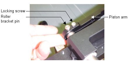
- On the side of the piston arm, release the locking screw and remove
the lock pin from the underside of the roller bracket pin (shown below),
and then lift the roller bracket pin out of the bracket.
- Remove the piston arm from the assembly.
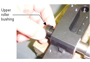
- Insert the upper roller bushing on the shaft (as shown below) and
attach it to the base of the assembly.
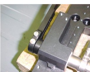
- Replace the piston arm, insert the securing pin and tighten the locking
screw (as shown in the picture below).
- Attach the roller to the assembly base, as follows:
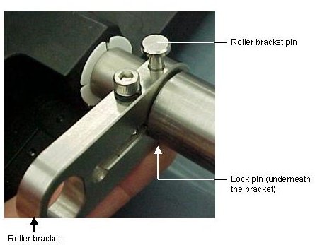
- On one side of the assembly base, remove the lock pin from the
underside of the roller bracket pin (shown below), and lift the
roller bracket pin out of the bracket.
- Push the bracket toward the outside of the
assembly base, as shown below.
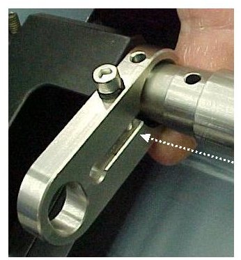
- Locate the two bushings and place one on each end of the roller
as shown below.
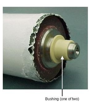
- On the other side of the assembly base, place one end of the roller
into the roller hole in the roller bracket.
- Push the bracket you moved in step 5b toward
the center of the assembly until the roller is held firmly by both
brackets.
- Replace the roller bracket pin and secure it in place using the
lock pin you previously removed.
- Remove the Allan® screw from one of the roller brackets
(shown below), apply Loctite® 242 to the screw and place
it back into the bracket. Firmly tighten the screw. Repeat on the
other side.
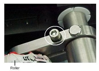
- Secure the two side-to-side detectors you previously removed to the
underside of the new assembly base, as shown below (one of two).
Note: Be sure to apply Loctite® to each
screw.
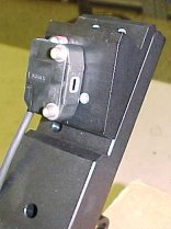
- Turn the assembly over and place the gripper assembly on the new,
single-roller assembly. Verify that:
- The actuator is positioned properly on the new assembly—the unload
gripper piston should be on the same side of the new assembly as the
unload roller piston.
- The actuator is properly seated on the pins on both sides of the
new assembly.
- Secure the actuator to the assembly using the five screws previously
removed.
Note: Be sure to apply Loctite® to each
screw.
Installing the unload roller assembly
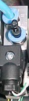
- From the right, side door, locate the unload roller air valve (solenoid)
in the manifold. If it does not have two air-tube nipples as
shown below, replace
the valve with the one included in the FCO kit.
Note: Connect the blue air tube to the valve as shown
below.
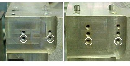
- From the front of the machine, install the new unload roller piston
by securing it to the two lowest securing holes on the Optomec, as shown
in the pictures below (use the screws previously removed).
Notes: The Optomec may have only two piston securing
holes. If it does, secure the piston to these two holes (the same holes
from which the piston was removed in step 6 in
Removing and dissembling the currently installed
unload roller assembly). Be sure to apply Loctite® to
each of the screws.
- From the rear of the machine, place the new unload roller assembly
on the Optomec and secure it in place using the eight screws previously
removed.
Notes: Make sure that the roller arm fits properly
inside the piston. Be sure to apply Loctite® to each screw.
- From the front of the machine, connect the piston to the new assembly
using the pin previously removed.
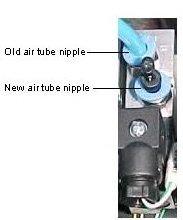
- Connect the blue air tube that is included in the FCO kit, to the
new air tube nipple on the unload roller air valve, as shown below.
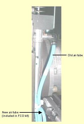
- Connect the two blue air tubes that are attached to the unload roller
air valve to the unload roller piston (connect the old blue tube to
the upper nipple, and the new tube to the lower nipple:
- From the rear of the machine, reconnect the following connectors:
Note: Be sure to secure all wires with plastic ties
so that they will not touch any moving parts during machine operation.
- Two side-to-side detectors.
- Unload gripper enable detector
- Unload gripper HP and EP detetctor.
- Unload roller HP and EP detector.
- Reattach the blue air tubes to the unload gripper piston.
Note: Attach the tube labeled "in" to the
innermost nipple, and the tube labeled "out" to the outermost
nipple.
- Remove the protective wrapping from the new roller, and clean the
roller with a lint-free cloth.
- Open the wall air pressure unit valve. Be sure that the air pressure
level is between 6 and 8 bar.
Testing unload roller function
- From the right side of the machine, manually activate and deactivate
the unload roller air valve by pushing the red button on the valve.
Verify that:
- There is no air leakage from either end of the blue air tubes
connected to the unload roller piston.
- The roller is not pressed forcefully on the drum (while the roller
is on the drum, gently lift it to verify that it only rests on the
drum by virtue of its own weight).
- Verify that the
HP detector is functioning properly. If it is not, adjust it as
required.
- Manually turn the drum and position the tail gripper slots underneath
the unload gripper pins.
- From the right side of the machine, manually activate and deactivate
the unload gripper air valve by pressing the red button on the valve.
Verify that:
- There is no air leakage from the blue air tubes connected to the
unload gripper piston.
- The unload gripper functions properly.
Note: In the event the old type vibration sensors assembly
is installed on your machine, you must readjust the vibration sensors
due to the extra weight of the one piece roller.
- Close all doors and start up the Lotem.
- Verify side-to-side function, and adjust, as required.
- Load, expose and process several plates of different sizes. Verify
that there are no pressure marks, and that all is working properly.
|

