

Home | Contact Us | Submit Troubleshooting Info | Search | Help
Output | Software Solutions | Proofing | Color, Screening and Calibration | Scanning | Digital Photography | Consumables | POS
Home | Contact Us | Submit Troubleshooting Info | Search | Help
Output | Software Solutions | Proofing | Color, Screening and Calibration | Scanning | Digital Photography | Consumables | POS
Description
Improving unload reliability of machines using plates up to 0.3 (mm).
|
Prepared By: Itai Peperovich |
FCO Kit No: 510F27648 |
|
Comp. Level: |
Machine S/N: |
|
Catalog No: 507F1L039 |
S/W Affected: |
|
Type of Change: Conditional |
Total Number of Pages: 5 |
|
Product Mgr: Nir Halup |
Approval Date: 03-05-2001 |
|
Product Support: Itai Peperovich |
Approval Date: 27-04-2001 |
|
Customer Support Mgr: Assaf Zach |
Approval Date: |
FCO 27847 - "Needle Bearing For Gripper", must be implemented with FCO 27648
1. Reason For Change
2. Description of Change
1. Replace all the head gripper assembly.
2. Replace the existing head spoilers with spring spoilers.
3. Change Procedure
1. From the GUI, open the front and rear doors.
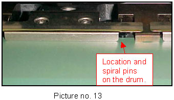
2. Mark the location of the spiral and the stopper pin spoiler on the drum.
3. Arrange the spoilers in a line so it is clear to what goes where. Make
sure you have the spoilers before removing the existing ones.
4. Open the screws ob each spoiler to remove all the existing head spoilers
from the drum (see picture no.1).
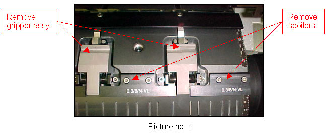
Note: Use loctite 242 on all screws and tighten with a torqmeter 20 (in/lb)
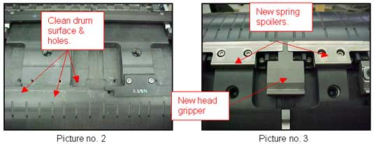
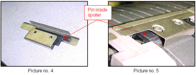
Note: Press the grippers with your hands and make sure the spoilers are moving up and down freely, without touching the screws head.
Note: Make sure the levers are lifting the spring spoiler and that they are not touching the drum surface.
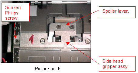
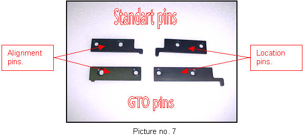
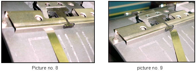
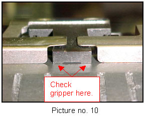
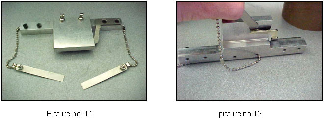
Note: To check pins attachment, look at it from straight-ahead and not from above (like with the old spoilers).
Go back to working status
5. Parts List
|
PART |
QTY
|
DESCRIPTION |
| 280A6A339 | 1 | SPRING LEVER (LEFT) |
| 280A6A340 | 1 | SPRING LEVER (RIGHT) |
| 290A2U025 | 1 | SPRING SPOILER RIGHT |
| 290A2U026 | 1 | SPRING SPOILER LEFT |
| 290A2U027 | 2 | SPRING SPOILER 90MM |
| 290A2U028 | 2 | SPRING SPOILER 100MM |
| 290A6A947 | 1 | LOCATION PIN |
| 290B7B121 | 1 | LOCATION PIN II FOR HALF-WEB |
| 290A6A955 | 1 | ALIGNMENT PIN FOR HALF-WEB |
| 290B7B119 | 1 | ALIGNMENT PIN |
| 291A2U029 | 2 | SPRING SPOILER 122MM |
| 291A2U030 | 2 | SPRING SPOILER 160MM |
| 374A00080 | 1 | PACKING LABEL-WHT |
| 380A05063 | 38 | SOC.HD.CAP STST 8-32X1/2" |
| 380G05040 | 4 | PHIL FLT HD STST 8-32*3/8" |
| 380J05040 | 2 | PHIL FLT HD STST 8-32*3/8" |
| 381A05002 | 2 | HEX NUT STST#8-32*1/8" |
| 382D11000 | 42 | SPRING L/W ST ST #8 |
| 480C10192 | 1 | ADH.RET.10CC LOCTITE 242 |
| 507A3E402 | 2 | SIDE HEAD GRIPPER ASSY |
| 507A3E677 | 7 | HEAD GRIPPER ASSY/ S. SPOILER |
| 431G01100 | 0.1 | ST SHIMES FOIL 0.5" 0.05 MM |
| 7!FCO-DOC | 1 | FCO DOCUMENT |
6. Attached Documentation
None.
7. Material Disposition
8. Logistics
Approved quantities:
|
CSA |
: |
40 |
|
CSE |
: |
40 |
|
CSAP |
: |
5 |
|
CSN |
: |
5 |
|
CSMA |
: |
5 |
|
Other |
: |
Schedule supplies for first lots
|
D.U |
Month |
QTY |
Month |
QTY |
Month |
QTY |
|
|
CSA |
: |
June |
20 |
July |
20 |
||
|
CSE |
: |
June |
20 |
July |
20 |
||
|
CSAP |
: |
June |
5 |
||||
|
CSN |
: |
June |
5 |
||||
|
CSMA |
: |
June |
5 |
||||
|
Other |
: |