Home | Contact Us | Submit Troubleshooting Info | Search | Help


    Output | Software Solutions | Proofing | Color, Screening and Calibration | Scanning | Digital Photography | Consumables | POS


Field Change Order #512-28458A Installing a cleaning brush onto the light detector hood

Important: Do not implement this FCO on platesetters that already have a debris remover installed.

Applies to


Lotem® 800 VL

FCO kit number: 512-28458A

Estimated implementation time: 1 hour


Priority: Conditional

Reason: Cleaning the optic head lens cover.

Description: Adds a lens cleaning brush to the light detector hood (cover).

Release date: 21 Aug 2003

Component


Light detector hood and brush assembly.

Problem


In situations where high-ablation plates are regularly used, plate ablation accumulates on both the optic head lens protector, and the light detector lens. This causes a noticeable decline in image quality, puts a strain on the laser diodes, and may ultimately cause diode failure.

Solution


This FCO adds a lens cleaning brush to the light detector hood.
Each time the carriage moves to the home position, the optic lens protector passes over the brush and any ablation (or other debris) that has settled on the lens protector is brushed off.
The brush prevents a buildup of debris on the lens protector, helps to maintain image quality and keeps the diodes in good working order.

Parts needed


Parts list
FCO kit #512-28458A includes the following parts:

Part

Qty

Description

252-03499A 1 Lens brush (for long lens)
500-00745A 1 Light detector hood + brush assy. (VL)
290A9C030 1 Brush protector
719-28458A 1 Optic head lens cleaning-FCO (for VL)

Procedure


This procedure includes the following steps:

  1. Removing the light detector and hood (cover).
  2. Checking the lens.
  3. Installing the light detector hood and brush assembly.
  4. Testing functionality.

Note: This FCO kit includes a long brush for platesetters with a short lens.

Removing the light detector hood (cover)

  1. In Lotem Controller, move the carriage to the center position (300).
  2. Open the rear door.
  3. Shut down the platesetter.
  4. Remove the rear upper panel.
  5. Disconnect the three unloading tray motor connectors and remove the unloading tray.
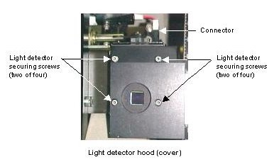
  6. Disconnect the connector on top of the light detector:
  7. Remove the four light detector screws (shown above), and carefully remove the light detector assembly from the platesetter.
    Important: Do not touch the light detector lens.
  8. Remove the light detector hood (cover).
  9. Clean the light detector lens with a cotton bud dipped in alcohol.

Checking the lens

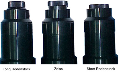
Platesetters are fitted with either a small lens (Short Rodenstock®) or a long lens (Long Rodenstock®, Zeiss®):


Note: The majority of platesetters contain a small lens. These type of lenses require a long brush (18 mm), whereas platesettters fitted with long lenses need a short brush (10 mm).

Check the type of lens installed on the platesetter.
If the platesetter is a Lotem 800 and/or has a long lens, see the procedure Replacing the long brush with a short brush before continuing with the following procedures.


Installing the light detector hood and brush assembly

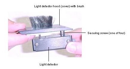
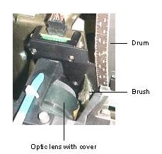
  1. Place the light detector hood (complete with brush) on the light detector:

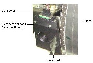
  2. Secure the light detector and hood into place by using four screws dipped in Loctite 242. The brush should face toward the drum:
  3. Reconnect the connector onto the top of the light detector.
  4. Clean the optic head lens protector with a cotton bud dipped into alcohol.
  5. If there is a buildup of ablation on the drum or other component of the platesetter, clean the relevant component.

Testing functionality

  1. With the rear door open, start up the platesetter.
  2. Insert cheaters.
  3. In Lotem Controller move the carriage to home position.
  4. When the optic head lens protector passes the light detector, check that:
    • The brush brushes the lens protector.
    • The optic head lens protector and the light detector hood do not collide.
  5. Remove the cheaters, replace the unloading tray and the rear upper panel, and close the rear door.
    Important: Make sure the three unloading tray motor connectors are reconnected.
  6. As soon as the working status toggles to Ready, check that all the laser diodes are functioning.
    If any of the diodes fail, check that the connector on the top of the light detector is properly plugged in and recheck the laser function. If the diodes still fail, refer to the escalation page.

Action required

  Material disposition

Dispose of the removed light detector.

Logistics

Approved quantities:

CSC Quantity
CAM 50
CEM 50
CAP 20
CJP 20
CMA 20
No limit  

Scheduled supplies for first lots:

Schedule CAM CAP CJP CEM CMA Other
02 Jul 03 50 20 20 50 20  


Lead time for additional FCO kits (orders beyond the approved quantities): 6 weeks.

Inventory in warehouses: N/A


Technical contact
 

Yaron Shifman

Date submitted
 

20 Aug 2003


    Copyright © 2005 Creo Inc. All rights reserved. Confidential. Back to top.