The Plate conveyor is supplied in a separate
package. It is recommended that two (2) people unpack and assemble the conveyor. Refer to
the following figures; the numbers in brackets, in the instructions below, identify the
various parts.
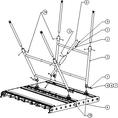
Open the packaging. The packaging includes the following
parts (Figure 2-13):
Upper assembly [4]; has two parts, front and back, where the
back part can fold toward the front part.
Two identical leg assemblies [3].
Leg adjuster assembly [8].
Small bag with screws and washers.
Remove the two Leg assemblies, the Legadjuster
and the bag of screws and other accessories (the Upperassembly should
remain in the packaging).
Open the inner protection cover of the Upper assembly
so that the side facing you is exposed (the other parts are assembled to the Upperassembly
while it is in the packaging).
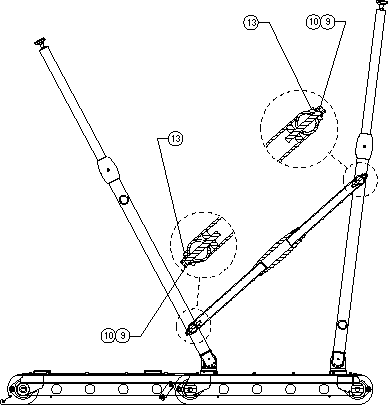
Refer to Figure 2-14 - connect the
two leg assemblies to the Upper assembly: each leg assembly is
connected with two shoulder screws [1]. The Legassembly orientation should
be so that the slots in the Leg assemblyhorizontalbar will enable
inserting the legadjuster screws [9]. Do not tighten the screws.
Note: If the leg assembly does
not fit into the upper assembly (item [15] inFigure
2-13), open the four screws that attach the leg assembly, make the necessary
adjustment and tighten the screws.
Connect the leg adjuster [8] to the two leg
assemblies:
Refer to Figure 2-13 - disconnect
the two parts of the legadjuster by releasing the set screws [2]. Note that
one part has a ruler printed on it.
Refer to Figure 2-14 - connect the
leg adjuster part with the ruler to the top bar of the front leg assembly.
Use screw [9], spring washer [10] and adjuster washer [13]. Do not tighten the screw.
Refer to Figure 2-14 - connect the
other part of the leg adjuster to the bottom bar of the rear legassembly.
Use screw [9], spring washer [10] and adjuster screw [13]. Do not tighten the screw.
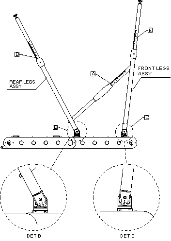
Refer to Figure 2-15 - using the
ruler printed on the leg adjuster, adjust the length according to the required
height (above).
Tighten the two set screws [2] shown in Figure 2-13.
Adjust the leg assemblies angle [3] to the upper
assembly [4] (Figure 2-13 and Figure
2-15):
There are sets of holes in the leg assembly and in
the upper assembly. Rotating the leg assembly will engage holes in the fixed
and mobile parts.
Note: It is important to adjust the front
leg assembly first.
Locate the correct hole for the front leg - see value
C in "Conveyor - Processor Interface" for
your processor. Match it with the corresponding hole in the upper assembly, by
rotating the leg.
Insert a screw [5], washer [7] and spring washer [6] into
the two holes of the front leg. Tighten the screws.
Locate the correct hole for the rear leg - see value B
in "Conveyor - Processor Interface"
for your processor. Match it with the corresponding hole in the upper assembly, by
rotating the leg.
Insert a screw [5], washer [7] and spring washer [6] into
the two holes of the rear leg. Tighten the screws.
Tighten the shoulder screws [1] that connect the upper
assembly with the legassembly (a total of 4 screws, 2 for each leg).
Adjust the height of each leg assembly:
Refer to Conveyor - Processor
Interface for the required leg assembly height for your processor. For the rear
leg - value D; for the front leg - value E.
Release both set screws [14] of each leg in the front leg
assembly, and in the back leg assembly.
Using the ruler printed on the leg, adjust the length of the
narrow part of each leg according to the above height.
Tighten the two set screws of the two legs of the front leg
assembly, and the back leg assembly.
At both ends of the leg adjuster, tighten screw [9]
that connects the leg adjuster to the leg assemblies.
Turn the Conveyor over, face up, so that it stands on its
legs (the back part should be folded on top of the front part).
Remove front tray of the
processor and connect the plate sensor to upper part of the conveyor.
A - length of leg adjuster ruler part
B - rear leg angle position
C - front leg angle position
D - length of rear leg ruler part
E - length of front leg ruler part
* Note: This processor is only
an example. CreoScitex does not recommend any specific company's product.
Figure 2-13: Plate conveyor assembly (1)
Figure 2-14: Plate conveyor assembly (2)
Figure 2-15: Plate conveyor assembly (3)
Attaching Plate Conveyor to
Platesetter
The Conveyor connects to the upper back panel of the
platesetter.
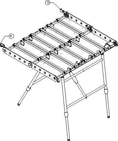
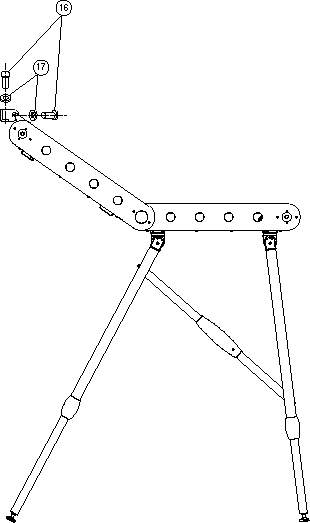
Refer to Figure 2-16 and Figure 2-17- attach the conveyor hooks [11, 12] to the
upper back panel of the platesetter, using the two screws [16] and two spring washers
[17]. Note that there is a left and right hook (in the figure, items [11] and [12]
respectively).
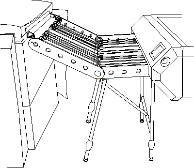
Refer to Figure 2-18 - hang the
front part of the upper assembly on the two hooks on the back panel of the
platesetter.
Verify that the conveyor is stable in its place. If needed,
fine-tune the height of the leg assemblies by adjusting the length of the ruler part of
the leg.
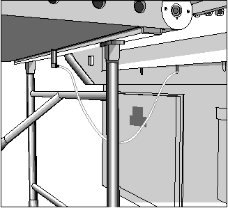
Pull out the conveyor power cable from inside the
platesetter (through the cable opening at the bottom).
Plug the conveyor power cable into the wiring plug adapter
attached to the upper assembly.
Attaching Plate Conveyor to
Processor
Place the processor near the conveyor, so that the plate
entrance at the front side of the processor is close to the conveyor (several mm
distance).
Adjust the processor height to the conveyor height: the
plate entrance of the processor should be at the same level as the upper strip of the
conveyor belts.
Some processors have platesensors that can be
connected to the conveyor. For these processors, connect the platesensor to
the appropriate opening in the front side of the upperassembly (see Figure 2-19).
Figure 2-16: Attaching Plate conveyor to platesetter (1)
Figure 2-17: Attaching Plate conveyor to platesetter (2)
Figure 2-18: Attaching Plate conveyor to platesetter (3)
Figure 2-19: Attaching plate sensor from the Processor to Plate conveyor
Parameter Settings in the
Platesetter
At the Operationmonitor, open the Utilities
menu.
Click on the Tools button.
Enter the Service password in the Password window.
From the extended Utilities menu, right click on
Lotem 800I/O object (in sw version 2.0).
In the I/O object menu, choose New Local.
Under SolenoidsUnloadConveyorSolenoid, set Open value to 1.
Under DetectorsUnloadConveyorDetector, set Open value to 1.
Restart the application.
Copyright
(c)1998 Scitex Corporation Ltd. All rights reserved. Certain names, logos,
designs, titles, words or phrases on this page may constitute trademarks, servicemarks,
or tradenames of CreoScitex Corporation Ltd. or other entities which may be
registered in certain jurisdictions.


 I/O object (in sw version 2.0).