Home | Contact Us | Submit Troubleshooting Info | Search | Help


    Output | Software Solutions | Proofing | Color, Screening and Calibration | Scanning | Digital Photography | Consumables | POS


Focus pre-load on Lotem


Product

 
  • Lotem™ 800
  • Lotem 400

Background


Precise control of optical focus requires a preset tension between the focus arm and the spring steel mounting plates. After the tension is set, it is normally maintained regardless of the focus calibration.

Use this procedure when replacing the focus motor or when the focus calibration procedure fails to establish a focus value within the recommended range of 300 to 400 focus motor steps.
Note: The factory pre-set range is new as of February 2002. The recommended range for older machines was 200 to 300 focus motor steps.

Prior to following the procedure, it is helpful to first understand the mechanical design of focus control.

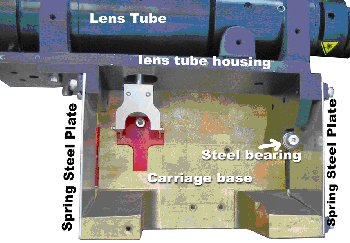
The lens tube housing is mounted on two brackets, which in turn, are mounted on the ends of two spring steel plates. The ends of the plates are secured to the base of the carriage, as shown below (lens tube and carriage base without the resolution and focus motors).

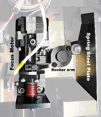
A rocker arm turns against a steel bearing that presses against the front spring steel plate, deforming it slightly.

Since the optic tube is mounted on the plates, it moves back and forth proportionately to the rotation of the rocker arm.

The rocker arm's movement is controlled by the focus stepper motor. The range of lens to drum focus adjustment for different plate thicknesses is very small, approximately 200 microns. To control such small movement, maintain a consistent setting, and ensure correlation of motor steps to lens movement. When the spring plate is under tension, the focus motor must begin turning (HP).

Tension is measured by measuring the movement of the optic tube as the focus motor begins to activate the rocker arm.


Requirements


Procedure

  To set the correct tension:
  1. Install the focus motor and coupling.
    Note: If the focus motor is already installed, proceed to step 2.
  2. Mount the focus motor on the carriage base using three 8-32 x 5/8" screws:
    1. Use a flat washer and a lockwasher with each screw.
    2. Before tightening the screws, push the motor towards the drum so that the rocker arm rests securely against the steel bearing; then tighten the screws.


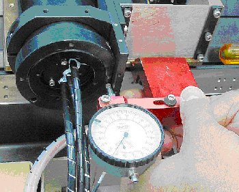
  3. Mount the jig with the dial indicator, positioning the dial indicator so that it is touching the optic tube, as shown below.


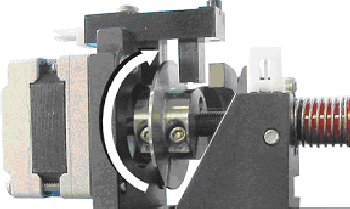
  4. Manually rotate the fine detector wheel clockwise while keeping an eye on the dial indicator. The indicator should move.


  5. Continue rotating the wheel slowly until the indicator stops moving (indicating the position at which there is no tension on the spring steel plate).
  6. Set the dial indicator to 0.
    Note: When rotating the fine detector, make sure your hand is not touching the spring.
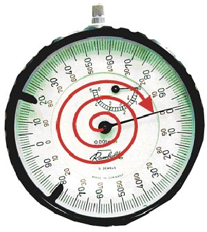
  7. Rotate the fine detector wheel counter clockwise until the dial indicator moves exactly 300 microns.
    Note: If the dial indicator reading is 100 microns after turning the fine detector 180 degrees; then 300 microns is equivalent to 1.5 revolutions.


    In the picture above, the dial indicator is rotated 1.5 revolutions (300 microns).

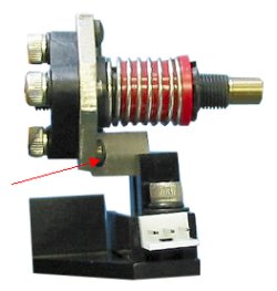
  8. Adjust the course flag detector, using a #4 Allan® key, so that the flag is located halfway into the detector.
    Note: Do not overly tighten the detector, you may have to move it later.


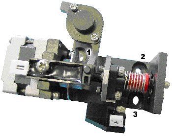
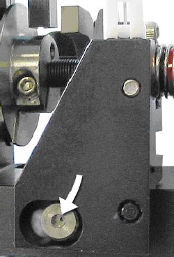
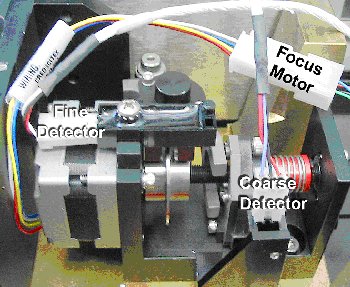
  9. Attach the motor cable and the two focus detector cables (fine and course), as shown below.


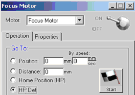
  10. From the GUI, open the Focus Motor and send it to the Home Position.


    Observe the indicator dial movement as the focus motor moves. It should move anywhere between 200 and 400 microns, immediately followed by a backward movement of 130 microns. If this is what happens, the preload setting is correct, and you can tighten the coarse HP detector.
  11. If the indicator moves more than 400 microns, there is not enough pressure on the spring steel plate. You need to move the coarse detector towards the optic tube.


    Note the limited distance that you can move the coarse detector within the oval hole in the detector's housing.

  12. If the indicator moves less than 200 microns, there is too much pressure on the spring steel plate. You need to move the coarse detector away from the optic tube.

Technical contact(s)
 

Content owner: Itai Peperovich
See the Escalation page for escalation contacts.

Date submitted
 

dd Feb 2003


    Copyright © 2005 Creo Inc. All rights reserved. Confidential. Back to top.

Popups / Tool Tips for this Page

   Close this popup...