(

 
    Home | Contact Us | Submit Troubleshooting Info | Search | Help


    Output | Software Solutions | Proofing | Color, Screening and Calibration | Scanning | Digital Photography | Consumables | POS


Laser Interlock Test


Product


Lotem family


Background


This procedure enables you to check the function of all laser interlocks, and to identify interlocks that are not functioning properly.


Requirements


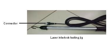
Laser interlock testing jig (p/n 504S4E151).


Procedure

 
  1. Close the PC controller application, and shut down the machine.
  2. Remove the rear, lower poanel and trapezoid panel.
  3. Locate the L-box power plug in the distribution box, and disconnect the L-box power connector.
  4. Connect the laser interlock testing jig connector (shown below) to the L-box power plug on the distribution box.
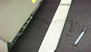
  5. Lay the laser interlock testing jig in a safe place on the floor, and replace the rear, lower panel, as shown below. Do not replace the rear, trapezoid panel.
    Note: Be careful not to step on the jig.
  6. Power up the machine. The jig indicates laser interlock function, as follows:
    • If one or more doors are not closed, the light in the jig is off.
    • If all doors are properly closed, the light in the jig is on.
    • If all doors are closed but one or more laser interlock is malfunctioning, the light in the jig is off.
  7. To verify the function of individual laser interlocks, open and close each door from the PC controller application, and verify that, in the GUI, the machine status changes appropriately, as described below:
    • Ready: When all doors are closed and the laser interlocks are functioning properly.
    • Off-line: When something is wrong, including one or more of the doors being open.
    • Service: When everything is functioning properly and one or more of the doors is open.
  8. When finished, close the PC controller application, and shut down the machine.
  9. Remove the rear, lower panel and disconnect the laser interlock testing jig connector from the L-box power plug on the distribution box.
  10. Reconnect the L-box power connector to the L-box power plug on the distribution box.
  11. Replace the rear, trapezoid panel, the rear, lower panel.
  12. Power up the machine.

Technical contact(s)
 

Content owner: Itai Peperovich
See the Escalation page for escalation contacts.

Date submitted
 

02 Jun 2002


    Copyright © 2005 Creo Inc. All rights reserved. Confidential. Back to top.