Procedure |
|
Parts:
| Part Number |
Part Description |
Quantity |
| 290B2U821 |
Valve control holder Lotem 800
|
1 |
| 344B25703 |
Union STR.6TO4MM tube EPDM
|
4 |
| 344B80000 |
Fitting straight 1/8NPT-6mm
|
6 |
| 344D57010 |
"T" union fit.D1=6 D2=4 D3=6 mm
|
15 |
| 344D57020 |
Union Y 3X6mm rapid conn
|
1 |
| 344D58010 |
"T" union fit.D1=8 D2=6 D3=8 mm
|
1 |
| 344F10131 |
Hose blue OD=6, ID=4mm polyure
|
6 |
| 344F10142 |
Tube, soft blk. OD=4, ID=2.5MM
|
3 |
| 347A53000 |
2/2-way N.C. sol.val.24VDC 1/8
|
2 |
| 374A00080 |
Packing label-wht
|
1 |
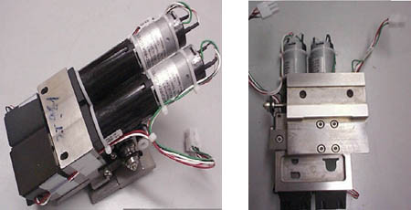
Click to view image of Lotem 800 variable punch kit: 
Hardware changes:
- Open top front door and right side door.
- Turn off the air pressure supply.
- Shut off the power from the mains.
- Assemble the new punch unit on the bar and place the diamond nut into
the T-slot on the punch bar.
Note: Punch connectors
9 and 10 are reserved for control purposes.
- Tighten the screw connecting the punch to the diamond nut. The diamond
nut also turns until it comes into contact with the wall of the T-slot.
Continue tightening the screw until the punch is secured firmly in place
on the bar.
- Take all measurements from the ruler on the punch bar.
- Assemble the new punch control valve, located on the right side of
the punch beam, to the mainframe. Use a 5/32 inch screw (10/32 hex head):
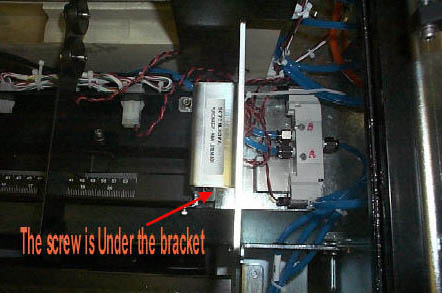
- Route the air tubes and the harness from the control valve to the
left side of the platesetter, behind the punch beam.
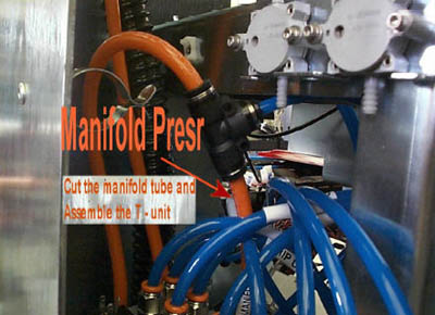
- Install the new air T connector on the main supply line, labeled “MANIFOLD
PRESR” (orange air tube):
- Connect the air tubes labeled “extend” to the extend side
of the swivel connectors of each new punch cylinder:
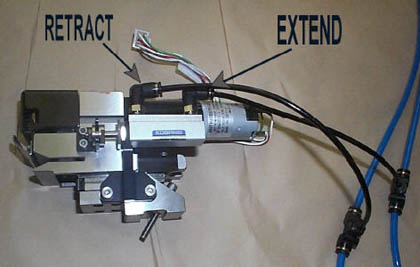
- Connect the air tubes labeled “Retract d” to the retract side
of the swivel connectors of each new punch cylinder.
- Trim excess length of air tubes.
- Connect the electrical connectors of the control valve harness to
the existing punch harness connectors 9 and 10, as labeled.
Software settings:
- Perform the following changes in the Lotem registry:
- Open all the required punch motors, including motors 9 and 10.
This requires changing the “Open” parameter value from 0
to 1.
- Open all the required punch motor detectors, including motors
9 and 10, by navigating to the Home Pos Detector
parameter (IO Objects\Punch Motor #09\Home Pos Detector) and change
the existing default value to None. Repeat this
for the #10 detector.
- On punch motors 9 and 10 - change the time out value from 15 sec
to 5 sec.
- Define the punch sets in the punch database as follows:
- For punch sets that include the double action punches, but do
not require the piston to be activated, configure them as usual.
(Do not include punch motors 9 and 10.)
- Include punch motors 9 and 10 for those punch sets that require
the piston to be activated.
- Close all the platesetter’s covers and test the punch variable
unit.
|
Test |
|
Note: Refer to the punch
setting configuration.
After all the punches have been installed, load a plate using the automatic
loading system:
- Punch the plate and then remove it for visual comparison with the
master template to confirm the
position of holes.
- If required, move the punches, positioning pin or the plate guide.
- Let the press operator install a plate on the press in order to verify
the correct position of the punches.
|

