Home | Contact Us | Submit Troubleshooting Info | Search | Help


    Output | Software Solutions | Proofing | Color, Screening and Calibration | Scanning | Digital Photography | Consumables | POS


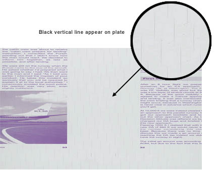
Preventing unwanted black vertical lines from appearing on the exposed image


Product

 
  • Lotem® 200
  • Lotem 400
  • Lotem 400 Quantum
  • Lotem 400 Xpose
  • Lotem 800
  • Lotem 800 II
  • Lotem 800 Quantum

Symptoms


Broken, black vertical lines appear on the exposed image:


Cause


The vertical lines may be caused by one of the following problems:

  • The carriage beam and groove require oil.
  • The carriage beam is over-oiled. This can also cause the carriage movement to be erratic.
  • The oil bracket has been incorrectly installed and consequently it rubs against the carriage beam. The friction between the carriage base and the carriage beam may cause the black vertical lines.
  • The lead screw is defective and/or the stepper motor coupling needs adjusting.
  • The Rulon® (felt) on the carriage base is defective and/or dry and cracked. This may cause too much friction between the carriage base and the carriage beam.
  • The carriage beam surface is dirty and/or scratched.
  • There is not enough resistance between the carriage base and the carriage beam.

Solution


Eliminate each of the following problems in the order that they appear:

Oil (part number 402-00172)
Make sure that the carriage beam is sufficiently lubricated. It is essential that the beam is neither over-nor under-oiled.
See How to clean and oil the V-block/carriage beam on all CIL devices.

Oil bracket
Make sure that the oil bracket is correctly positioned in relation to the carriage beam. Check whether the bracket screws are aligned. Visually inspect the oil bracket for any signs of damage. If required, replace the oil bracket:

  • Lotem Fiberheads (part number 252-08459A)
  • Lotem Quantums (part number 291A5A397)

Leadscrew and coupling motor
Make sure that the leadscrew and coupling motor are correctly adjusted for optimal flexibility.
See Leadscrew and stepper motor coupling adjustment.

Important: Remove the lead screw and check the following

Carriage base resistance
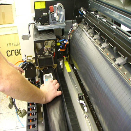
Use a dynamometer to check the carriage base resistance against the carriage beam:

  • Unplug all the head cables.
  • Connect a dynamometer to the carriage base and measure the carriage base resistance:
  • The carriage and the head weight resistance on the carriage beam should be between 5 kg and 7 kg. If the resistance is greater, you may have to replace the carriage beam and the carriage base.

Rulon (felt)
Inspect the Rulon for dryness and cracks. If the Rulon is damaged, the carriage may have to be replaced.

Scratches and dirt
Make sure that the carriage beam surface is clean and scratch-free. If deep scratches are evident, both the carriage beam and carriage base may need to be replaced.

Important: If you suspect that the carriage beam needs replacing, contact a CSS-PSS/PSM.


Parts List

 
Description
Part Number
Carriage assembly (Quantum) 507C3E204

Oil brackets

  • Lotem Fiberheads: 252-08459A
  • Lotem Quantums: 291A5A397
Silicon oil 402-00172


Technical contact(s)
 

Yaron Shifman

Submitted by
 

Yaron Shifman

Date submitted
 

05 May 2004


    Copyright © 2005 Creo Inc. All rights reserved. Confidential. Back to top.