Home | Contact Us | Submit Troubleshooting Info | Search | Help
Output | Software Solutions | Proofing | Color, Screening and Calibration | Scanning | Digital Photography | Consumables | POS
Home | Contact Us | Submit Troubleshooting Info | Search | Help
Output | Software Solutions | Proofing | Color, Screening and Calibration | Scanning | Digital Photography | Consumables | POS
Product |
Lotem® 800 |
||
Component |
Power failure protector board assembly (part number 503-00020B). |
||
Symptoms |
After installing a power failure protector board on a Lotem 800 platesetter (FCO #512-03310A), one or all of the following components may fail to respond:
|
||
Cause |
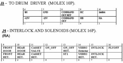
Due to the fact that the failure protector board is situated between the distribution box (J4 connector) and the remainder of the Lotem’s wiring, a fault with one of the board’s Molex® pins could prevent power from reaching a vital component. |
||
Solution |
Do the following to verify if the power failure protector board is preventing power from reaching vital components:
|
||
See also |
|||
Technical contact(s) |
|||
Submitted by |
|||
Date submitted |
24 May 2004 |
||