| |
- Quit Lotem 800 Controller software.
- Remove the existing drum registration pins from the drum.
- Replace the existing pins with the modified drum registration pins:
- Drum with eccentric registration pins:
4 x drum registration pins (part numbers 252-01384A,
252-01389A, 252-01388A, 252-01386A)
- Drum with regular registration pins:
2 x drum registration pins (290A6A947, 290B7B121)
2 x GTO spiral punch assembly (507D3E488)
- Install the two spiral punch assemblies (507D3E488).
- Connect the two punch motors to any available Molex®
connectors, located on the punch harness.
- Open RegEdit and do the following:
- Amend the value of ..\EXPOSE\Plate Edge Detection Enable
to 0.
- Amend the value of ..\EXPOSE\Spiral Punch Motor Enable
to 1.
- Update the spiral punch motor numbers, on which the spiral punch
motors are mounted, by accessing: \IO OBJECTS\PUNCH SYSTEM\Punch
system\Punch Spiral Unit
and
\IO OBJECTS\PUNCH SYSTEM\Punch system\Secondary Punch Unit
Example: Enter Punch
Motor #03 for the Punch Spiral Unit parameter, and enter
Punch Motor #04 for the Secondary Punch Unit parameter.
- Open the relevant punch motors and detectors that you have just
assembled, by amending their Open parameter value
to 1.
- In Lotem 800 Controller software, locate Media Advanced Properties
and amend the media Positioning Type from Edge
to Punch.
Note: If it is not possible
to amend the positioning type in Lotem 800 Controller software, perform
the following actions:
- In Microsoft® Windows® Explorer®,
locate the MediaDataBase folder.
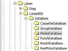
- In the MediaDataBase folder, double click the
media file you wish to amend. (If the Open with.. dialog box opens,
select Notepad and click OK. You
will only be asked this prompt once.)
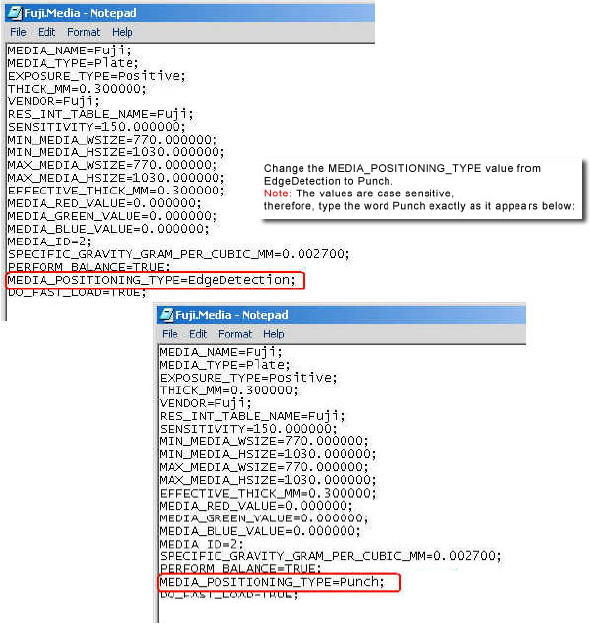
Manually amend the MEDIA_POSITIONING_TYPE value
from EdgeDetection to Punch.
Important: The values
are case sensitive. Therefore, when typing the word Punch,
make sure the letter P is typed in uppercase and the
remaining letters (u, n, c,
h) are typed in lowercase:
- After amending the value, restart Lotem 800 Controller software.
- Manually adjust the spiral notches on the plate to approximately 4.4
mm, and then check that the image parallelism to plate edge is in compliance
with the specifications.
- Ensure that the image is centered on the plate, on the sub scan axis,
by amending the following registry parameter:
MACHINE\Height Start Image Area for Plate (mm).
- In Service Shell, ensure that the start of the image exposure begins
from the top edge of the plate by amending the following:
Set gc\mshift and mshift small.
|

