Home | Contact Us | Submit Troubleshooting Info | Search | Help


    Output | Software Solutions | Proofing | Color, Screening and Calibration | Scanning | Digital Photography | Consumables | POS


Elevation calibration test and adjustment for ThermoFlex Mid and Narrow


Product

 
  • Kodak® ThermoFlex® Mid
  • ThermoFlex Narrow

Background


The objective of the elevation calibration test is to find the correct elevation angle of the optical head. When the elevation angle is correct, all 24 or 48 beams are in focus. Incorrect elevation results in a different optimal focus value for beams on each side of the V groove.

Elevation does not depend on plate type, size or thickness. The test and adjustment (if required) can be performed on any plate that the customer uses.


Requirements

 
  • Focus value obtained in the Focus Calibration Test
  • Densitometer
  • Microscope
  • Flexo plate(s)
  • Offset plate(s) if the configuration includes offset option
  • Fine dial gauge
  • Elevation jig
  • Elevation plate jig
  • Elevation indicator

Procedure


Expose two focus tests on the same plate. The first focus test uses only the first five beams while the second test uses only the last five beams. If the elevation angle is correct, the optimal focus value will be the same (+/- a 10 micron tolerance) for both tests.

This procedure contains two stages:

Testing elevation

First test:

  1. Perform the focus test on only the first five and last five diodes with th following changes:
    • In Test Focus Values (Steps):
      From—type the optimal focus value that you found in the focus test -30.
      To—type the optimal focus value that you found in the focus test +30.
    • Use 7 steps.
    • Use the following intensity values:
      • 660 mV diode/flexo plate: 300 mV
      • 1 W diode/flexo plate: 500 mV
      • 1 W diode/offset plate: 120 mV
  2. In ThermoFlex Controller, select the laser group to test:
    1. Select Utilities>Hardware>Expose System>Laser System and right-click Laser Group.
    2. In the Properties: Laser Group dialog box, change the value of the Last Expose Laser Active parameter to 4.
      Only the first five beams will be tested.

    Note: Make sure that the nozzle is as far as possible from the drum.

  3. Expose the test file.

Second test

  1. In ThermoFlex Controller, change the laser group to test:
    1. Select Utilities>Hardware>Expose System>Laser System and right-click Laser Group.
    2. In the Properties: Laser Group dialog box, make the following changes:
      • Last Expose Laser Active—23 (or 47, as required).
      • First Expose Laser Active—19 (or 43, as required).
      Only the last five beams will be tested.
  2. In the Offset box, type an offset value around the drum so that the batch of strips in the second test are exposed below the batch of strips in the first test.

    Note: Make sure that the nozzle is as far as possible from the drum.
  3. Expose the test file.

To determine whether the elevation angle of the optical head is correct, examine the results of the two sets of exposed strips and determine the best focus value for each set.

  • If the two best focus values are equal or less than ten microns apart, the elevation angle is correct.
  • If the two best focus values are more than ten microns apart, proceed to adjusting elevation.

Adjusting elevation

Note: The numbers in brackets identify the parts shown in the diagram in the Image section.

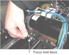
  1. Remove the focus limit block from the carriage.
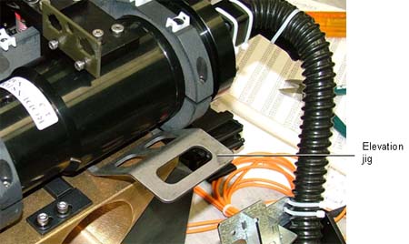
  2. Connect the elevation jig [3] to the optical head.
    This will help support the lens and help with initial adjustment of the head.
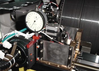
  3. Connect the fine dial gauge[4] to the elevation jig.

Note: Before proceeding, write down the value on the fine dial gauge [4].

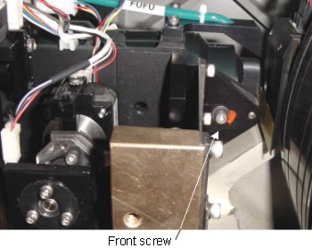
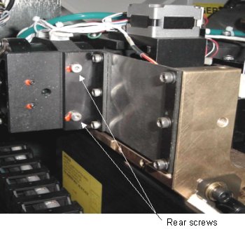
  1. Carefully loosen the three screws [2] that secure the optical head until the friction is strong enough to hold the optical head but still enable its adjustment.
    Note: Be careful that the lens tube does not drop completely.

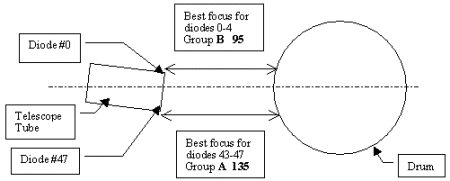
  2. Calculate the value (C) to move the telescope tube, using the best focus values for the groups of 5 diodes that you measured in steps 2 (B) and 7 (A) of the Testing elevation section, for example:
    • A—Diodes 43-47 (or 19-23) = 135
    • B—Diodes 0-4 (see step 2 in the testing elevation section ) = 95
    Subtract A from B and divide by 2: (B-A)/2=C
  3. Calculate the direction of the telescope tube adjustment according to the results you received in step 5:
    • A>B—lower the back of the telescope tube by C microns.
    • A<B—raise the back of the telescope tube by C microns.
  4. To change the elevation angle of the optical head, rotate the pin [1] and move the optical head. Watch the dial indicator as you move the optical head.
    For example, if the focus value for B is 95 microns and the focus value for A is 135 microns, move the optical head 0.2 mm upward.
  5. Tighten the three screws that secure the optical head.

Images


click image to enlarge


Test

  Repeat the test procedure, and readjust the elevation angle until the test results for both sets of lasers are identical, with a 20 micron tolerance.

Technical contact(s)
 

Content owner: Viki Arviv
See the Escalation page for escalation contacts.

Date submitted
 

22 Jun 2004


    Copyright © 2005 Creo Inc. All rights reserved. Confidential. Back to top.