Procedure
|
|
Before performing the focus test:
- Check the focus stopper location. There should be the minimum amount
of space between the optic tube and the optic tube bracket, as shown
following.
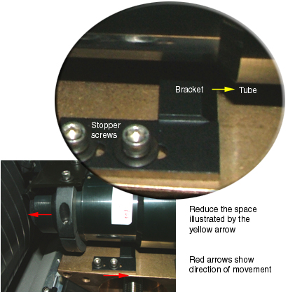
To move the focus stopper to the proper location:
- Move the carriage to any location along the drum.
- Move the focus motor to the maximum location.
- For wide focus range, move the focus motor to 5000.
- For earlier versions, move the focus motor to 2800.
- On the optic tube stopper, loosen the two hex screws and then
move the stopper until the optic tube bracket touches the optic
tube.
- Lock the stopper in place by tightening the two hex screws.
- Important: Move the nozzle as
far away from the drum as possible.
Failure to move the nozzle as far away from the drum as possible before
setting the forcus for each media thickness may cause irrepairable damage
to the platesetter.
Note: The focus stepper motor value
is dependent on the plate type, so repeat this test for each plate type
and thickness that the customer uses.
Calibrating Focus
- Load a plate.
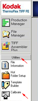
- In TIFF FE, from the Launch Pad, select Utilities > Calibrate.
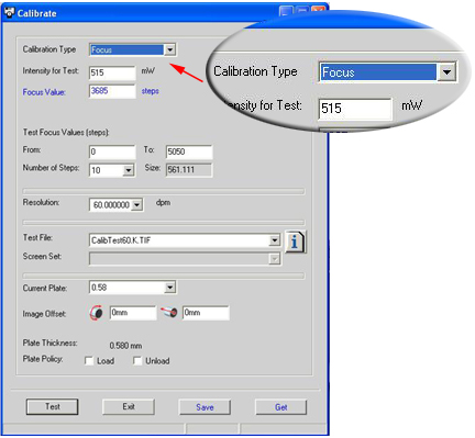
- In the Calibration Type box, select Focus.
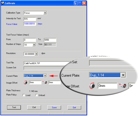
- In the Current Plate list, select the Plate that you
are using.
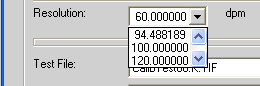
- Select the appropriate Resolution.
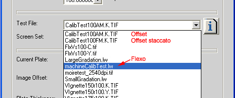
- Select the relevant test file according to the type of plate:
- Flexo—select machineCalibTest.lw
- Offset—select CalibTest100AM.K.TIF
- Offset Staccato—select CalibTest100FM.K.TIF
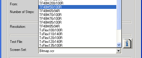
Note: If your plate type is Flexo, you must also select the relevant
screenset. For example:
- Define the Image offset values:
- Horizontal offset—The value around the drum in mm
- Vertical offset—The value along the drum in mm
If you use the same plate for several tests, define different offset
values for each test.
Note: The (0,0) offset coordinate is located at the upper-left
corner of the plate.
Note: The parameters in steps 8-11 are different for the coarse
test and the fine test. Perform the first test using the coarse parameter
values, and the second test using the best results from the coarse test,
and the fine parameter values listed in steps 8-11.
- Select the Intensity for Test parameter value according to
the following table.
| Diode strength and plate type |
660 mV diode/
flexo plate |
1 W diode/
flexo plate |
1 W diode/
offset plate |
| Intensity Narrow |
coarse: 600 mV
fine: 300 mV |
coarse: 900 mV
fine: 500 mV |
coarse: 140 mV
fine: 120 mV |
| Intensity Mid |
coarse: 600 mV
fine: 300 mV |
coarse: 900 mV
fine: 500 mV |
coarse: 170 mV
fine: 120 mV |
- Set the Test Focus Values [Steps] From and To
range:
- Coarse test: Find the target focus from the following table
and enter a range of ±100.
| Plate thickness (mm) |
Target focus value
in microns for media thickness range |
| 0.1 to 2.54 mm |
0.76 to 3.2 mm |
1.14 to 3.94 mm |
Wide range |
| 0.17 |
2540 |
not supported |
not supported |
4950 |
| 0.7 |
1940 |
2640 |
not supported |
4420 |
| 1.14 |
1500 |
2200 |
2940 |
3980 |
| 1.7 |
940 |
1640 |
2380 |
3420 |
| 2.54 |
100 |
800 |
1540 |
2580 |
| 3.2 |
not supported |
140 |
880 |
1920 |
| 3.94 |
not supported |
not supported |
140 |
1180 |
| 5 |
not relevant |
not relevant |
not relevant |
120 |
Note: The focus values in the table are in microns.
Focus value should be within a 30-micron deviation from the table
value.
If the plate thickness you need does not appear in the table:
Non-wide range: Click focus value calculation table to automatically
calculate the focus value for any plate thickness.
Wide range: Find the target focus for one of the listed thickness
and calculate the target focus for other thicknesses according to
the following formula:
Unknown focus value = known focus value - [(unknown
plate thickness - known plate thickness) x 1000]
For example: Using a 0.17 mm thick plate's required focus of 4950,
find the focus value for a 0.3 mm plate thickness:
X = 4950 - [(0.3-0.17) x 1000]
X = 4950 - [0.13 x 1000]
X = 4950 - 130
X = 4820
- Fine test: For the fine-tuning test, the range is the best
step that you find in the coarse test ±50).
- Set the Number of Steps: Coarse = 5, Fine = 11.
- In the database, select the Drum Speed according to the following
table.
| Diode strength and plate type |
660 mV diode/
flexo plate |
1 W diode/
flexo plate |
1 W diode/
offset plate |
| Narrow |
170 rpm
|
220 rpm
|
500 rpm
|
| Mid |
120 rpm
|
170 rpm
|
500 rpm
|
- Move the carriage so that the lens is in front of the loaded plate.
- Move the focus motor to the maximum motor step at which you plan to
expose and check that the nozzle does not collide with the loaded plate.
- Before exposing the plate, measure the plate thickness and update
the media definition.
Important: Alert the customer to always measure the media thickness
before exposing, and to update the thickness in the media definition
dialog box, if required.
- Close any open doors and verify that the platesetter is in Ready
mode.
- Click Test to initiate the focus test. The application performs
several exposures.
Note: After you perform the coarse test, you may need to calibrate
resolution and delay before performing the fine test.
Select the best focus value:
- Remove the black layer in the corners of the measured plate so that
you can see the clean plate.
- Regular plates—use masking tape to remove the black layer
- BASF Nyloprint plates—use water to remove the black layer
- PCI Film—use a blade to scrape the mask off
- Calibrate the densitometer so that the density reading of the clean
corner (without the masking tape) is 0.
- Measure the density in the solid area.
- Select the clearest strip with the lowest density and use its value
as your focus value.
- If the target focus value is very different than expected, proceed
as follows:
- Move the carriage to middle position.
- Move the focus motor to the optimal focus value that you found
for that plate.
- Record the position of the large and small hands on the dial.
- Move the focus motor to the required position according to the
table.
- Remove the stopper bracket.
- Loosen the two screws that secure the optic tube.
- Manually move the optic tube to the position that you recorded
on the dial.
- Reinstall the stopper bracket and adjust its position.
- Tighten the two screws that secure the optic tube.
- Expose the plate and check the results.
- In ThermoFlex Controller, in Media definition, type the focus value.
This value is the optimal focus for the tested plate thickness.
- If required, repeat the test for other plate types and thicknesses.
Note: The thickness of individual plates can be different between
batches according to vendor specification. You must use the correct
focus value for each plate definition. The device does not compensate
by calculating the correct value for other plate thicknesses.
- Adjust the nozzle position.
|

