Background |
|
A properly adjusted anti-collision detector helps prevent collisions
between a plate and the carriage head. The anti-collision detector contains
two identical optic fibers and an optic sensor that function as follows:
- Lower optic fiber: transmitter, not moveable
- Upper optic fiber: receiver, moveable for fine-tuning
- Optic sensor: connects to both optic fibers on one end and to the
anti-collision detector on the other end
If the signal sent by the lower optic fiber to the upper optic fiber
is broken, the optic sensor detects the presence of a plate. The focus
lens moves to home position (HP), which prevents the plate from colliding
with the carriage head.
After replacing or installing an anti-collision detector, you must adjust
the detector.
|
Procedure |
|
Before you begin:
- Load a 20 x 20 cm (8 x 8 in.) plate on the drum.
- If your platesetter is ThermoFlex Mid II, after
you load the plate, open the service door on
the ThermoFlex Mid II, or the front door on the ThermoFlex Mid or Narrow
platesetter.
- On the ThermoFlex Mid or Narrow platesetter, open the loading tray.
- Insert a motor
interlock cheater.
- In the ThermoFlex Controller software, send the carriage to the position
that will bring it in front of the plate.
- Send the focus motor to the location that is appropriate for the plate
on the drum.
Installing the receiver and transmitter:
- Disconnect the focus motor connector.
Note: Because the focus motor returns to HP when you cheat the
anti-collision detector, you must disconnect the focus motor now.
- In the optic fiber holders, place the optic fibers so that the hollows
in the optic fibers face each other. The receiver (upper optic fiber)
hollow is facing down, and the transmitter (lower optic fiber) hollow
is facing up.
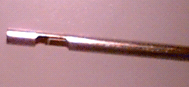
Optic fiber hollow facing down
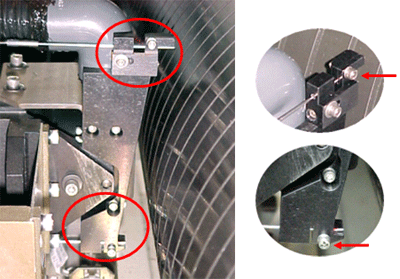
Nozzle assembly
- Verify that the optic fibers do not protrude, and secure them by tightening
the screws.
- Remove the optic sensor cover.
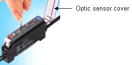
- On the optic sensor, push down the handle.

Optic sensor
- Insert the ends of the optic fibers into the optic sensor.
- Confirm that the lower (red) LED in the nozzle assembly is on.
If the upper LED in the nozzle assembly is on, in the optic sensor,
switch the optic fibers.
- Push up the handle to lock the optic fibers in place.
Adjustment Procedure
To set the optic sensor switches:
- Using the screwdriver from the kit, set the switches on the optic
sensor as indicated in the following table.
| Switch Name |
Set To |
|
| Fine / Turbo |
Turbo |
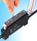 |
| Off.D / On.D / Off |
Off |
| D.On /L.On |
D.On |
| Potentiometer |
Max. |
- With the optic head in front of the drum, adjust the sensor potentiometer
to the maximum position and verify that the green LED is on.
Note: If the green LED is not on, rotate the potentiometer until
it turns on.
- Hold a 7/64" hex key between the transmitter and the receiver.
The red LED in the optic sensor should be on. When you remove the hex
key, the red LED should turn off. If the red LED in the optic sensor
remains on, it indicates that the hollows in the optic fibers are not
facing each other.
- Manually turn the drum and verify that the red LED is off and that
the green LED is on. The red LED should be off when the plate is in
front of the nozzle assembly. If the red LED is on, increase the sensitivity
of the optic sensor.
- In the ThermoFlex Controller software, open the Anti-collision detector
dialog box and verify that the LED status matches the actual status
of the LED.
- Red LED on: detector status on
- Green LED on: detector status off
- Stack five pieces of masking tape, one on top of another, to form
one thick piece of tape, and apply it horizontally across the top or
bottom edge of the plate.
- Manually turn the drum. When the tape passes between the transmitter
and the receiver, verify that the red LED in the optic sensor is on.
This indicates that the optic sensor detects the excess thickness.
- Continue to manually turn the drum until only the plate (not the tape)
is between the transmitter and the receiver, and verify that the red
LED turns off and the green LED turns on.
- Continue to manually turn the drum until only the bare drum is between
the transmitter and the receiver, and verify that the red LED remains
off and the green LED remains on.
- Remove one piece of tape and manually turn the drum. Verify that the
red LED is off.
The status of the green light is not relevant to this step.
Note: If the red LED is on, open the 7/64" hex screw, move
the upper nozzle assembly forward or backward, and adjust the potentiometer,
until the red LED is off.
- Tighten the 7/64" hex screw, and verify that the red LED remains
off.
- Apply the piece of tape that you removed in step 10, manually rotate
the drum, and verify that the red LED turns on.
Note: If the red LED is off, repeat the adjustment.
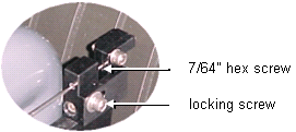
- When the adjustment is completed, tighten the locking screw.
- Return the optic sensor cover to protect the sensor.
- Remove the thick layer of tape, manually turn the drum, and verify
that the red LED is off and that the green LED remains on.
- Connect the focus motor connector.
- Remove the drum interlock cheater.
- On the ThermoFlex Mid or Narrow platesetter, close the loading/unloading
tray.
- Close any open doors on the platesetter.
|

