Home | Contact Us | Submit Troubleshooting Info | Search | Help


    Output | Software Solutions | Proofing | Color, Screening and Calibration | Scanning | Digital Photography | Consumables | POS


Anti-collision detector replacement and adjustment on ThermoFlex Mid and Narrow


Product

 
  • ThermoFlex® Mid
  • ThermoFlex Mid II
  • ThermoFlex Narrow

Background


Collisions between the plate and the carriage head can occur when a plate thicker than the set thickness value is mounted on the drum, or when the plate was not properly attached to the drum.

This procedure describes how to install and adjust the anti-collision detector (or plate detector) to prevent collisions.

The anti-collision detector contains two identical optic fibers and an optic sensor that function as follows:

  • Lower optic fiber—transmitter, not moveable
  • Upper optic fiber—receiver, moveable for fine-tuning
  • Optic sensor—connects to both optic fibers on one end and to the anti-collision detector on the other

If the signal sent by the lower optic fiber to the upper optic fiber is broken, the optic sensor detects the presence of a plate. This prevents the plate from colliding with the carriage head.


Procedure


Before you begin

  • Verify that the platesetter has the plate detector wiring required for the optic sensor.
  • Verify that Controller software version 1.20.12 or higher is installed.
  1. In Controller, move the carriage to middle position.
    • ThermoFlex Narrow—400
    • ThermoFlex Mid—600
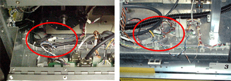
  2. Access the plate detector wiring:
    • Mid II
      1. In Controller, open the service doors.
      2. Exit Controller, turn off the platesetter, and turn off the main power to the platesetter.
      3. From the back of the platesetter, look for wiring labeled "Plate Detector"
    • Narrow and Mid
      1. In Controller, open the relevant doors:
        • Narrow—open the front door.
        • Mid—open the front and back doors.
      2. Exit Controller, turn off the platesetter, and turn off the main power to the platesetter.
      3. Manually open the right door and remove the front panel.
      4. Open the loading/unloading tray.
      5. Remove the four screws from the black cover above the L-box and remove the black cover.
      6. From the right side of the platesetter, look for wiring labeled "Plate Detector".
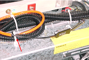
  3. Connect the optic sensor connector to the anti-collision (plate detector) connector.
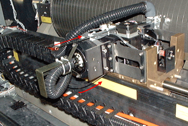
  4. Thread the optic fibers through the orange hose and route them through the fiber optic chain to the carriage.
  5. Route the upper optic fiber along the black hose to the nozzle assembly and the lower optic fiber under the spring leaves to the nozzle assembly.
  6. Perform the Anti-collision detector adjustment procedure.

Technical contact(s)
 

Content owner: Viki Arviv
See the Escalation page for escalation contacts.

Date submitted
 

25 Feb 2002


    Copyright © 2005 Creo Inc. All rights reserved. Confidential. Back to top.