Procedure |
|
This procedure contains the following sections:
- In Controller, send the carriage to the middle position.
- In Controller, open the relevant door(s) to enable access to the carriage,
and open the unload tray if required.
Note: On some of the older models, you must remove the unload
tray by removing the four screws.
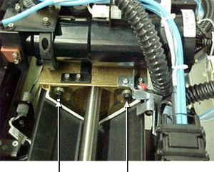
- Remove the two hex screws that secure the oil bracket to the carriage
and remove the oil bracket.
- Insert a motor cheater, and then send the carriage to EP.
- Exit the application, turn off the device, and disconnect the power
supply from the wall socket.
- Open the rear door, the front door, the side doors and the rear panels
of the device, as required.
- Remove the two screws that connect the chain to the mainframe (at
the end of the chain on the underside).
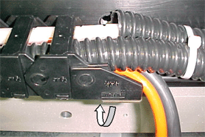
- Cut the cable ties that hold the debris removal tubes, the fiber optic
threads, and the anti-collision fibers.
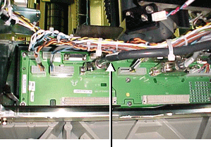
- From the Local mother board, disconnect the focus and resolution motors'
connector.
- Remove the Philips® screw from the flange that secures the fiber optics
tube and the debris removal tube.
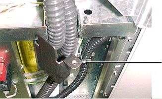
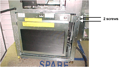
- Remove the two hex screws that secure the L-box and pull the L-box
slightly out.
- From the L-box, disconnect the TSP cable connector and the E-box cable
connector.
- Remove the 11 screws that secure the L-box to the frame.
Warning: When the screws are removed, the L-box rests on a platform
and is not secured by anything.
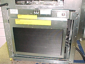
- Carefully pull the L-box out about one meter from its position in
the device, slide a trolley under the L-box, raise the trolley until
it touches the L-box, and then slowly pull the L-Box out until it is
on the trolley.
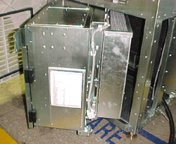
- Remove the local board.
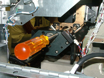
- With the special hex key, remove the three hex screws that secure
the lead screw coupling to the carriage.
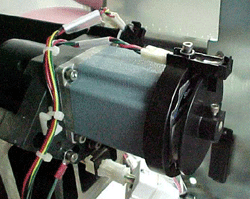
- Disconnect the following:
- Stepper connector
- Fine and coarse stepper detectors
- Ground cable
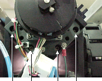
- Remove the four hex screws that secure the house bearing, and pull
out the leadscrew.
- Remove the carriage, including all wiring.
Note: When you have completed the procedure, pack the L-box in
the upgraded L-box package, and return the old L-Box to Billerica Shipping
and Receiving. If you do not have an RMA number, reference the SP number.
- Unpack the new L-box, put the new L-Box and head on the trolley, and
move them close to the Thermoflex. Raise the trolley to bring the L-Box
to the proper height to be secured to the chassis.
- Place the carriage on the beam.
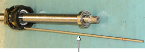
- Insert the jig into the leadscrew coupling, as shown, with the jig
in the hole that is parallel to the flat side of the coupling.
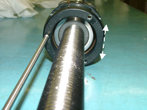
- Make sure that the jig is in the bottom hole, and insert the leadscrew.
Note: The placement of the jig in the bottom hole ensures that
the leadscrew is inserted in the proper location.
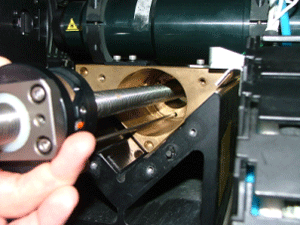
- With the special hex key, tighten the two hex screws that secure the
leadcrew coupling to the carriage.
- Remove the jig from the leadscrew assembly, and tighten the third
hex screw that secure the leadscrew coupling to the carriage.
- Insert and tighten the four hex screws that secure the house bearing.
- Connect the following:
- Stepper connector
- Fine and coarse stepper detectors
- Ground cable
- Insert the upgraded L-box into the device.
- Secure the L-box to the frame with the 11 screws you removed earlier
in step 13.
- Connect the TSP and E-box cable connectors to the L-box.
- Insert and tighten the two hex screws that secure the L-box.
- Insert and tighten the Philips screw in the flange that secures the
fiber optics tube and the debris removal tube.
- Connect the focus and resolution motors' connector to the local mother
board.
- Secure the debris removal tubes, the fiber optic threads, and the
anti-collision fibers in place with cable ties.
- Insert and tighten the two screws that connect the chain to the mainframe.
- Insert and tighten the three hex screws that secure the lead screw
coupling to the carriage.
- Connect the power supply to the wall socket.
- Close (or install) the unload tray.
- Close the rear panels and all the doors of the device.
- Turn on the platesetter.
After you complete the hardware upgrade, you must change some of the
parameters, described following.
- In the registry, select HKEY_LOCAL_MACHINE\SOFTWARE\Scitex\ Projects\LOTEMFLEXO\IO
OBJECTS\LASER GROUP\Laser Group and change the Max Possible Laser
Power parameter from 610 to 900.
- In the registry, select HKEY_LOCAL_MACHINE\SOFTWARE\Scitex \Projects\LOTEMFLEXO\IO
OBJECTS\NEW LOCAL \LDT\Light Detector and change the following parameters:
- High Dac Factor—3.5 or less
- Low Dac Factor—3.5 or less
Note: The following are the maximum drum speed possibilities that
exist in the V-speed configuration for Mid devices:
| Description |
Drum Speed [RPM]
|
Throughput
File size: Full Format [min] |
Drum Speed [RPM]
|
Throughput
File size: Full Format [min] |
| BASF - ACE DII 1.7 Nyloflex |
170
|
15
|
160
|
16
|
| BASF - FAH-D II 1.7 Nyloflex |
160
|
16
|
160
|
16
|
| Dupont - Cyrel DPS 1.7 |
180
|
14
|
170
|
15
|
| BASF - FAH-D II 1.14 Nyloflex |
180
|
14
|
170
|
15
|
| Dupont - Cyrel DPI 1.14 |
190
|
14
|
170
|
15
|
- If the number of diodes in the L-Box increased from 23 to 47 (if not,
proceed to step 4):
In the registry, browse to HKEY_LOCAL_MACHINE \SOFTWARE\Scitex \Projects\LOTEMFLEXO
and modify the following parameters:
- Default Last Laser Number—change from 23 to 47
(select EXPOSE).
- Last Expose Laser Active—change from 23 to 47
(select IO OBJECTS\LASER GROUP\Laser Group).
- Last Laser Active—change from 23 to 47
(select IO OBJECTS\LASER GROUP\Laser Group).
- Update the laser factors:
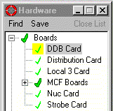
- In the Hardware Tree, browse to Boards and right-click
DDB Card.
- In the DDB dialog box, in the Lasers Factor section, click
Reset All to 0.
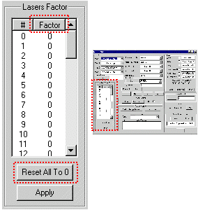
- Change the Factor for each diode according to the data sheet
in the upgrade kit.
|