Home | Contact Us | Submit Troubleshooting Info | Search | Help


    Output | Software Solutions | Proofing | Color, Screening and Calibration | Scanning | Digital Photography | Consumables | POS


Replacing the Wide Focus Motor on ThermoFlex Mid and Narrow


Product

 
  • Kodak® ThermoFlex® Mid II
  • ThermoFlex Mid
  • ThermoFlex Narrow

Background


This document describes how to replace the wide focus motor, and set the preload. The proper preload helps ensure the correct pressure on the focus spring so that each focus motor step is real movement of the focus lens.
Important: This is not an upgrade procedure. This procedure applies only to devices that already have a wide focus motor.


Requirements


Prerequisites

  • Local3 board
  • ThermoFlex Controller software version 1.31.350.002

Tools

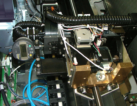
  • Digital indicator for wide focus system (690-00174A)
  • Focus adjustment jig (291B5A539)

Procedure


Note: This procedure is written for the ThermoFlex Mid II, but also applies to the Mid and Narrow versions.

Replacing the wide focus assembly

  1. In ThermoFlex Controller, click the Preventative Maintenance button.
  2. Exit ThermoFlex Controller and shut down the platesetter.
  3. Remove the upper back panel.
  4. Disconnect the following wiring connectors:
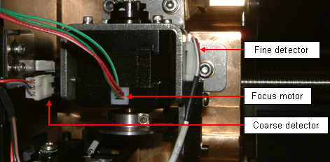
    • Coarse detector
    • Fine detector
    • Focus motor

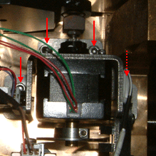
  1. Remove the four hex screws and then remove the wide focus motor assembly.
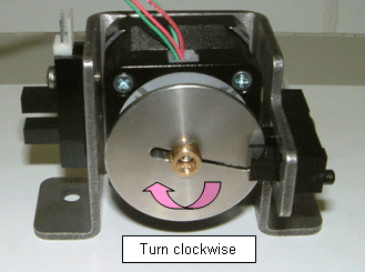
  2. From the rear of the new motor, turn the disk clockwise to rotate the shaft inward completely.


  3. When the shaft is as far in as possible, turn the disk counter counterclockwise 1/3 rotation.
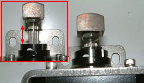
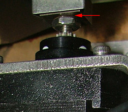
  4. Position the new assembly so that the edge of the shaft just touches the bracket.
  5. Secure the focus motor assembly with the four hex screws that you removed in step 5.
  6. Connect the wiring connectors.
  7. Turn on the platesetter and start Controller.

Setting preload

Before you begin, connect the focus jig.

To set the coarse detector:

  1. Make sure there is a gap between the end of the shaft and the focus assembly. Then, slowly rotate the fine disk in a counter-clockwise direction while watching the gauge.
    When the dial starts to move (indicating that the end of the shaft is touching the telescope), set the gauge to 0.
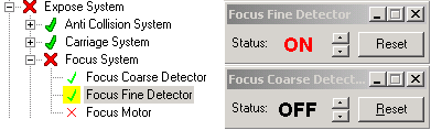
  2. In the Hardware tree, select Expose system>Focus System and double-click each of the following to open their dialog boxes:
    • Focus Coarse Detector
    • Focus Fine Detector

  3. Rotate the disk until the dial moves to 340 microns. At the 340 micron step, look at your monitor and confirm that the Focus Coarse Detector Status changes from On to OFF. If the detector status remains ON, proceed to step 4.
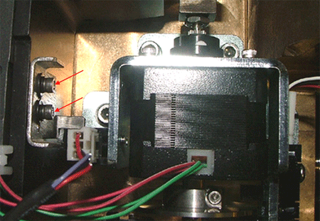
  4. With a hex key, open the coarse detector flag screw.
  5. Move the coarse detector flag until the status of the detector changes to OFF.
  6. Close the coarse detector flag screw.

To set the fine detector:

  1. Rotate the disk counterclockwise 200 microns until the dial points to 540 microns.
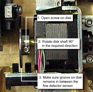
  2. Use a hex key to open the screw on the focus disk.
  3. Rotate the disk until the groove on the disk is inside the fine detector:
  4. Tighten the screw on the focus disk.
  5. Send the focus motor to HP.
  6. When the focus motor is at HP, set the focus jig dial to 0.
  7. Disconnect the forus motor wiring.
  8. Rotate the disk clockwise until the axel is disconnected from the disk.
    The dial should read 540 ± 40.
  9. Close all doors and panels.
  10. Perform calibration. (See Calibration Tests Overview .)

Technical contact(s)
 

Content owner: Viki Arviv
See the Escalation page for escalation contacts.

Date submitted
 

17 Mar 2005


    Copyright © 2005 Creo Inc. All rights reserved. Confidential. Back to top.