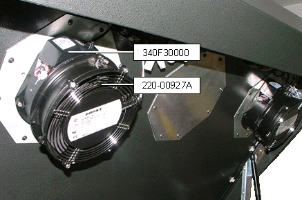
Solution:
- Check humidity:
- Verify that the humidity is 55 degrees, +/-5.
- If humidity cannot be adjusted, connect a GND cable (220-01731A):
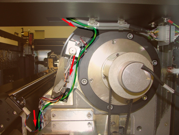
Thread the GND cable from the service door, as shown, down toward
the floor of the mainframe near the clutch.
Note: To add the GND cable to the other cable harnesses, cut the cable
ties, and then secure the GND cable to the harness with new cable
ties.
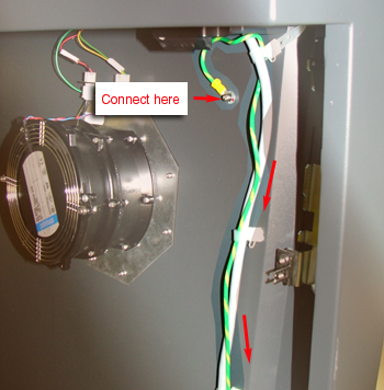
Connect GND cable to the service door
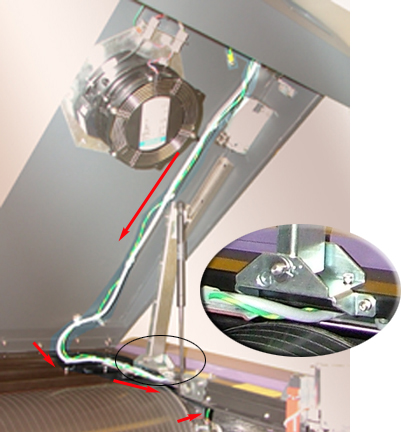
Route the GND cable down toward the drum and the side door.
Route the GND cable toward the clutch
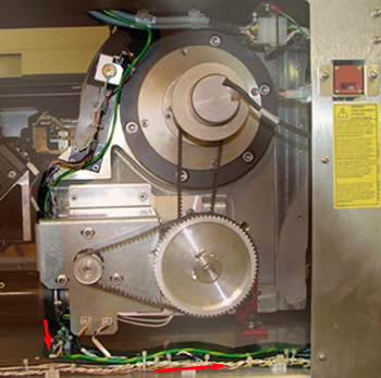
Route the GND cable along the mainframe alongside the clutch
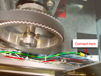
Connect the GND cable to the connector on the mainframe near
the clutch.
- Determine which part of the clutch is sliding:
- If the clutch and clutch plate are sliding, increase the friction
between the two parts.
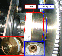
- In the gear locker, loosen the two set screws.
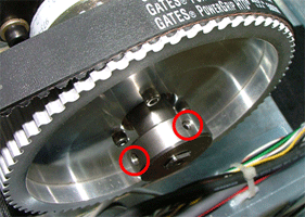
- Adjust the clutch and clutch plate so that they are tightly pressed
against each other, and then tighten the two set screws.
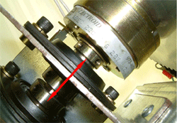
- If the clutch and shaft are sliding, the set screw in the inner
shaft of the clutch has come loose, causing the clutch to slide and
stop the drum from rotating. Replace the slow motor (clutch) assembly
by implementing FCO 512-00336A.
- Align the loading guide:
- Cut a plate to the height of the loading guide. Make sure that the
plate's corner angles are 90°.
- Align the plate on the loading table with the right edge as close
as possible to the loading guide.
- Begin to load the plate with the leading edge of the plate along
the scribe line.
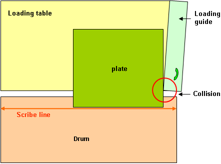
The plate's right edge touches the loading guide at only one point.
- Loosen the loading guide screws and align the guide with the right
side of the plate.
- With the loading guide aligned against the plate, tighten the loading
guide screws.
- Complete the loading guide sequence.
- When the plate is on the drum, measure the distance from each right
corner of the plate to the edge of the drum. The measurements should
be equal, with a tolerance of 1 mm (0.4 in.).
Note: The image location may have changed with the loading guide
location. Expose a test file, examine the location of the image, and adjust
the height-start image-area parameters as required.