Procedure |
|
Assembling the unloading conveyor
Attaching the unloading conveyor to the platesetter
Attaching the unloading conveyor to the processor
Configuring the unloading conveyor
Assembling the unloading conveyor
- Open the unloading conveyor packaging.
The packaging includes the following parts:
- Upper assembly [4]; has two parts, front and back, where the back
part can fold toward the front part.
- Two identical leg assemblies [3].
- Leg adjuster assembly [8].
- Small bag containing screws and washers.
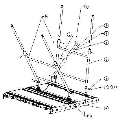
- Remove the two leg assemblies, the leg adjuster, the bag of screws
and other accessories. At this stage, there is no need to remove the
upper assembly in the packaging.
- Open the inner protection cover of the upper assembly so that the
side facing you is exposed.
- Connect the two leg assemblies to the upper assembly. Each leg assembly
is connected with two shoulder screws [1]. The leg assembly orientation
should be so that the slots in the leg assembly horizontal bar will
enable inserting the leg adjuster screws [9].
Notes:
- Do not tighten the screws.
- If the leg assembly does not fit into the upper assembly [15],
then open the four screws that attach the leg assembly, make the
necessary adjustments and tighten the screws.
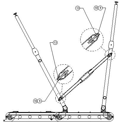
- Connect the leg adjuster [8] to the two leg assemblies:
- Disconnect the two parts of the leg adjuster by releasing the
set screws [2].
Note: One part of
the leg adjuster has a ruler printed on it.
- Connect the leg adjuster part with the ruler to the top bar of
the front leg assembly. Use screw [9], spring washer [10] and adjuster
washer [13].
Do not tighten the screw.
- Connect the other part of the leg adjuster to the bottom bar of
the rear leg assembly. Use screw [9], spring washer [10] and adjuster
screw [13].
Do not tighten the screw.
- Find out the make of processor at the customer’s site, and
the required leg adjuster height for that processor.
- Use the ruler printed on the leg adjuster, to adjust the length
according to the required height.
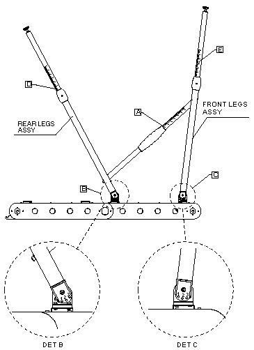
- Tighten the two set screws [2].
- Adjust the leg assemblies angle [3] to the upper assembly [4].
Note: There are sets of
holes in the leg assembly and in the upper assembly. Rotating the leg
assembly will engage holes in the fixed and mobile parts.
Important: Adjust the
front leg assembly first.
- Locate the correct hole for the front leg of the processor. Match
it with the corresponding hole in the upper assembly, by rotating
the leg.
- Insert a screw [5], washer [7] and spring washer [6] into the
two holes of the front leg. Tighten the screws.
- Locate the correct hole for the rear leg of the processor. Match
it with the corresponding hole in the upper assembly, by rotating
the leg.
- Insert a screw [5], washer [7] and spring washer [6] into the
two holes of the rear leg. Tighten the screws.
- Tighten the shoulder screws [1] that connect the upper assembly with
the leg assembly (a total of 4 screws, 2 for each leg).
- Adjust the height of each leg assembly.
- Release both set screws [14] of each leg in the front leg assembly,
and in the back leg assembly.
- Using the ruler printed on the leg, adjust the length of the narrow
part of each leg according to the above height.
- Tighten the two set screws of the two legs of the front leg assembly,
and the back leg assembly.
- At both ends of the leg adjuster, tighten screw [9] that connects
the leg adjuster to the leg assemblies.
Turn the conveyor over, face up, so that it stands on its legs (the
back part should be folded on top of the front part).
Attaching the unloading conveyor to the platesetter
The unloading conveyor connects to the upper back panel of the
platesetter.
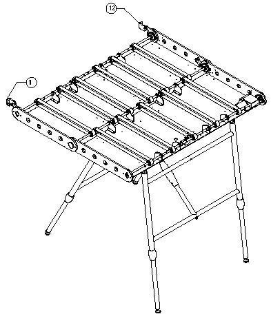
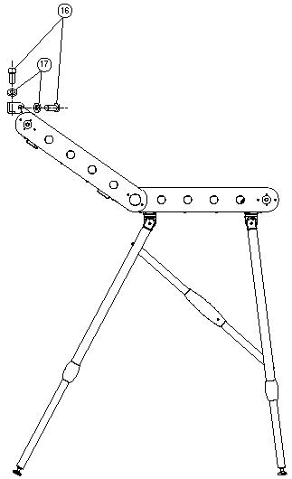
- Attach the conveyor hooks [1, 12] to the upper back panel of the platesetter,
using the two screws [16] and two spring washers [17]. Note that there
is a left and right hook (in the figure, items [1] and [12] respectively).
The left and right hooks are not interchangeable.
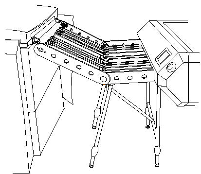
- Hang the front part of the upper assembly on the two hooks on the
back panel of the platesetter.
- Verify that the unloading conveyor is stable in its place. If needed,
fine-tune the height of the leg assemblies by adjusting the length of
the ruler part of the leg.
Attaching the unloading conveyor to the processor
- Place the processor near the unloading conveyor, so that the plate
entrance at the front side of the processor is close to the unloading
conveyor (several mm distance).
- Adjust the processor height to the unloading conveyor height: the
plate entrance of the processor should be at the same level as the upper
strip of the unloading conveyor belts.
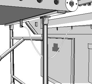
- Some processors have plate sensors that can be connected to the unloading
conveyor. For these processors, connect the plate sensor to the appropriate
opening in the front side of the upper assembly.
Configuring the unloading conveyor
There are two methods for configuring the unloading conveyor— a
quicker manual method, or a slower automatic method.
Automatic configuration
- If required, install Magnus Controller.
- In Magnus Controller’s Install Shield dialog box, select
Straight Conveyor. The unloading conveyor’s parameters
are automatically amended to reflect the use of a straight unloading
conveyor.
Manual configuration
- If required, install Magnus Controller.
- Manually update the unloading conveyor parameters. The parameters
are accessed from within the Magnus 800 parameters:
HKEY_LOCAL_MACHINE\SOFTWARE\Kodak\Magnus800
- Amend the value of the following unloading conveyor parameter values
to 1 (as shown below):
- Software systems\Device system\Device general params\Unloading
conveyor Type installed (N=0, S=1, R=2, L=3, S+L=4; S+R=5, Rot=6,
3rdP=7) = 1.
- Platesetter\Unload Conveyor 1 option\MSB IOObjects\DC motorsd\Unloading
straight conveyor motor\Open = 1.
- Platesetter\Unload Conveyor 1 option\MSB IOObjects\DC motors\Unloading
front conveyor detector\Open = 1.
- Close the registry and restart Magnus Controller.
|

