Procedure |
|
Calibrating the alignment system
- Obtain a punched reference plate.
- Remove the alignment system.
- Place the alignment system onto the chassis. Make sure you can access
the fine homing disc.
- Connect the alignment motor connector and the optical sensor detector
to the connectors located on the left side of the alignment system.
- In the Hardware Tree:
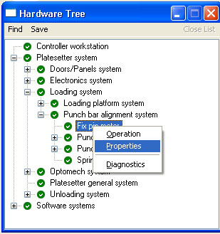
- Locate the Fix pin motor parameter (Platesetter/Loading
system/Punch bar alignment system/Fix pin motor).
- Right-click the Fix pin motor parameter and select Properties
from the list:
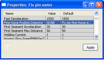
- The Properties: Fix pin motor dialog box appears.
Change the default value of the Fine Home Position Detector to NONE:
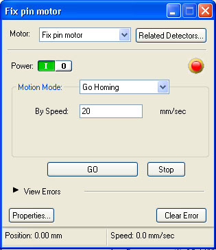
- In Magnus 800 Controller, send the fix pin motor to its home position
at a speed of 20 mm/sec:
- Make sure the groove on the fine homing disc is situated approximately
180° from the fine detector:
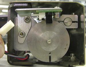
If the disc needs to be repositioned, release its screw and manually
rotate the disc until the groove is approximately 180° from the
fine detector. Tighten the screw.
- Slide the alignment system back into the platesetter:
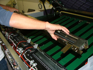
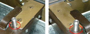
- Make sure the alignment system is flush against the two fixed pins
on the optomech assembly:
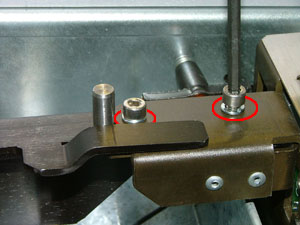
- Use a 4-mm hex key to insert and tighten the four screws that secure
the alignment system to the optomech assembly:
- In the Hardware Tree:
- Locate the Fix pin motor parameter (Platesetter/Loading
system/Punch bar alignment system/Fix pin motor).
- Right-click the Fix pin motor parameter and select Properties
from the list. The Properties: Fix pin motor dialog box appears.
- Change the value of the Fine Home Position Detector back to its
default value (Ctrl+D):
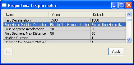
- In Magnus 800 Controller, send the fix pin motor and the spring pin
motor to their home position at a speed of 20 mm/sec.
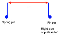
- On the platesetter, use a tape measure to measure the distance between
the two pins. For an accurate measurement, make sure there is no tension
on the spring pin. The distance between the pins is referred to as L.
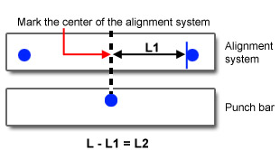
- Locate the zero on the punch beam’s ruler. Use a long ruler to
mark this corresponding point on the alignment system:
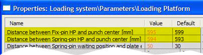
- In the Hardware Tree, locate the two plate positioning adjusting parameters
(Software system/Loading system/Parameters/Loading Platform):
- Distance between Fix-pin HP and punch center [mm]
- referred to as L1.
- Distance between Spring-pin HP and punch center [mm]
- referred to as L2.
- Restart Magnus 800 Controller in order for the changes to take effect.
Calibrating the plate width
- Amend the value of the following parameter to 0:
Magnus 800/ Software system/Loading system/Parameters/Loading Platform/
Spring pin alignment load- small plate [mm].
- Load a plate with the following dimensions: 381 mm x 330 mm x 0.15 mm.
Alternatively, either load a plate with the smallest dimensions, or
load the most sensitive plate available.
- Check the spring pin and make sure of the following:
- Pin only touches the plate.
- Pin is not pressing too hard on the plate.
- Pin is not located too far from the plate.
Important: If the
pin is pressing too hard on the plate, or if it is too far from
the plate, amend the following parameter: Distance between
Spring-pin HP and punch center [mm]. This parameter is
also referred to as L2.
- Use a tape measure to measure the width of the plate.
Note: The plate width
is the side of the plate that runs across the drum (as opposed to the
length of the plate, which is the side of the plate wrapped around the
drum).
Write down the plate’s dimensions.
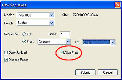
- In the New Sequence dialog box, select the Align Plate
check box:
- Load and punch a plate.
- If you need to move the plate toward the fixed pin, subtract the deviation
amount from the value of L1 and add it to the value of L2.
If you need to move the plate toward the spring pin, add the deviation
amount to the value of L1 and subtract it from the value of L2.
- Open the log file: C:\Magnus\Magnus800\Log\General
- In the log file, perform a search (Ctrl+F) on the
words plate width.
- Make sure the plate width in the log file matches the actual measured
plate width. The plate widths must match to within ±0.5 mm.
- If the discrepancy between the two measurements is ±0.5 mm,
then amend the Hardware Tree as described in the next step.
- In the Hardware Tree:
- Locate the Loading system parameter (Software systems\Loading
system).
- Right-click the Loading system parameter and select Properties
from the list:
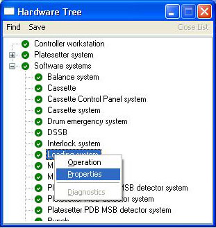
The Properties dialog box appears.
- Double-click Parameters.
- Double-click Loading platform and locate the
Offset for plate width calculation [mm] parameter:
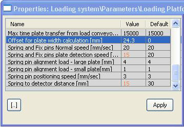
- If the width of the measured plate is longer than the width that
appears in the log file, then add the difference
to parameter’s value in the Hardware Tree.
- If the width of the measured plate is shorter than the width that
appears in the log file, then subtract the difference
from the parameter’s value in the Hardware Tree.
Example:
Measured plate width = 1030 mm
Plate width in log file = 1029 mm
Amend Offset for plate width calculation [mm] parameter
by +1 (1030 - 1029 = 1):
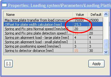
|

