Home | Contact Us | Submit Troubleshooting Info | Search | Help


    Output | Software Solutions | Proofing | Color, Screening and Calibration | Scanning | Digital Photography | Consumables | POS


Replacing the alignment system optical sensors on the Magnus 800 platesetter


Product


Kodak® Magnus™ 800 platesetter


Background


There are two alignment optical sensors located near to the alignment system pins:

  • Spring-pin optical sensor
  • Fixed-pin optical sensor

This procedure describes how to remove and replace the alignment system optical sensors.


Procedure


Removing the alignment system optical sensors

Important: The following procedure involves handling the optical sensors. When handling the sensors, avoid touching the sensitive optical sensor windows.

Removing the spring-pin optical sensor

  1. Remove the alignment system.
  2. Remove the seven screws securing the alignment system cover to the alignment system.
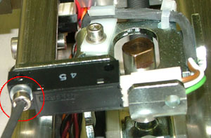
  3. Use a 2.5-mm hex key to remove the screw securing the spring-pin optical sensor (part number 138A00100) to the alignment system:


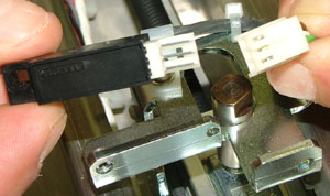
  4. Disconnect the connector from the spring-pin optical sensor:


Removing the fixed-pin optical sensor

  1. In Magnus 800 Controller software, click Raise Platform to raise the platesetter loading platform.
  2. Use a 2.5-mm hex key to remove the screw securing the fixed-pin optical sensor (part number 138A00100) to the alignment system.
  3. Disconnect the connector from the spring-pin optical sensor.

Replacing the alignment system optical sensors

Important: Unless otherwise stated, coat all screws in Loctite® 242 adhesive.

  1. Connect the optical sensor connector to the optical sensor. (View image)
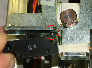
  2. Align the pin on the sensor with the hole on the alignment system.
    Use a 2.5-mm hex key to insert and tighten the screw securing the optical sensor to the alignment system:


  3. If required, reinstall the alignment system cover onto the alignment system, and then reinstall the alignment system.
  4. Manually lower the loading platform.

Test

 
  1. Load and unload several plates of different size and thickness.
  2. Make sure the process runs smoothly and continuously.

Technical contact(s)
 

Content owner: Yaron Shifman
See the Escalation page for escalation contacts.

Date submitted
 

22 Feb 2005


    Copyright © 2005 Creo Inc. All rights reserved. Confidential. Back to top.