Procedure |
|
- Turn off the Magnus 800 processor and Mercury V6 processor.
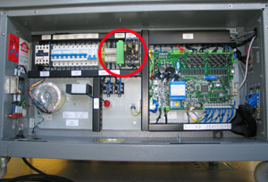
- Connect the Mercury V6 processor to a Magnus 800 platesetter:
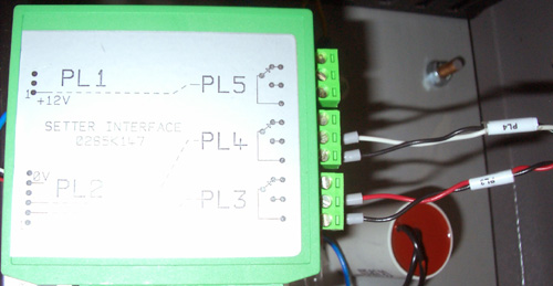
- Connect the Magnus 800 interface cable labeled PL4 to the PL4
connector on the processor.
- Connect the Magnus 800 interface cable labeled PL3 to the PL3
connector on the processor.
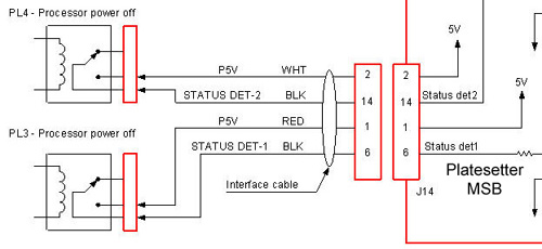
- Connect the opposing end of the Magnus 800 interface cable to
J14 on the platesetter MSB.
- Turn on the Magnus 800 processor and Mercury V6 processor.
- Configure the processor user settings:
- On the processor’s touch screen, press 1
to access the Main menu screen.
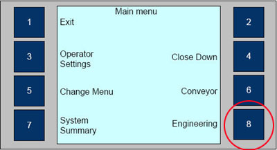
- In the Main menu screen, press 8 to access the
Engineering screen. The Engineering screen is password protected
and the password changes every four hours. The password is required
in order to modify the IP address. Obtain a password
and access the Engineering screen.
- From the Engineering screen, access the Configure User Setter
screen (Engineering > Settings > Plate Setter > Configure
User Setter).
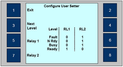
- In the Configure User Setter screen, press Next Level
(3) to move the cursor down through the list - Fault,
N Rdy, Busy, and Ready.
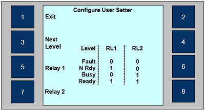
When one of the levels is selected press either Relay 1
or Relay 2 to change the relay state to 1 (on)
or 0 (off). Amend the relay state for RL1 and RL2 as depicted in
the image below:
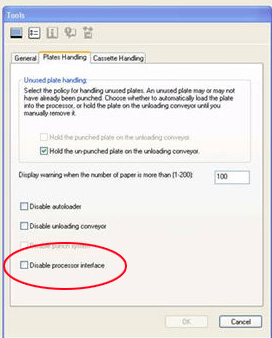
- In Magnus 800 Controller software, clear the Disable processor
interface check box.
- In the Magnus 800 Controller software Mode pane, click Tools.
- In the Tools dialog box, click the Plates Handling
tab.
- Make sure the Disable processor interface check
box is cleared.
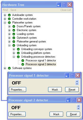
- In the Magnus 800 Registry, verify both processor signal detectors
are open (HKEY_LOCAL_MACHINE\SOFTWARE\Kodak\Magnus800\Platesetter\Platesetter
base\MSB IOObjects\Detectors\Processor signal x).
Interpreting processor related messages
The processor screen displays the status of the processor. Magnus 800
Controller software receives two signals from the processor and generates
a corresponding message relating to the status of the processor signals,
as described in the following table:
|
Processor
|
Platesetter
|
|
Status
|
Proc.
Signal 1
|
Proc.
Signal 2
|
Status Interpretation
|
Det. 1
|
Det. 2
|
|
READY
|
1
|
1
|
Processor can receive and process
plates.
|
On
|
On
|
|
WARNING
|
1
|
0
|
Processor can receive and process
plates. The Magnus 800 Controller software warns operator about
impending maintenance.
|
On
|
Off
|
|
BUSY*/
NOT READY*
|
0
|
1
|
Processor cannot receive a plate
because it is either warming up or working to maximum capacity.
|
Off
|
On
|
|
FAULT**
|
0
|
0
|
Processor cannot receive a plate.
Requires operator intervention.
|
Off
|
Off
|
*When
the processor displays BUSY/NOT READY, the following
message appears in the Magnus 800 Controller software:
Busy: IDS_PROCESSOR_UNLOADING_CONTINUE_UNLOAD

        Verify that the processor status is ready and able to receive a plate.

        Click Continue or click Unload to automatically unload the plate from
        the unloading platform. If the problem persists, in the Operation panel
        click Stop. To continue working, you can disable the processor interface.
**When
the processor displays FAULT, the following message appears
in the Magnus 800 Controller software:
Error: IDS_PROCESSOR_UNLOADING_CONTINUE_REMOVE

        Verify that the processor status is ready and able to receive a plate.

        Click Continue or remove the plate manually from the unloading conveyor
        and click Media Removed.

        If the problem persists, in the Operation panel click Stop. To continue
        working, you can disable the processor interface.
|