| |
The Light Tight kit is only effective if the site is adequately prepared.
Before installing the kit, implement the following working conditions:
- The Magnus 800 platesetter, multi-cassette autoloader, and plate stack
must be located in a room with a yellow light source.
- The Magnus 800 computer and workstation may be in either the same
room as the device, or an adjoining room.
- Install nine black adhesive labels (518-02634A) on the autoloader:
- Install six adhesive labels (three per each side) over the holes
located on the interior of the autoloader.
Note: Black adhesive label 1 is larger
than labels 2 and 3.
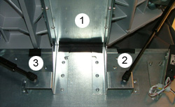
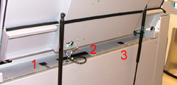
- Install three black adhesive labels over the holes located on
the underside of the loading conveyor.
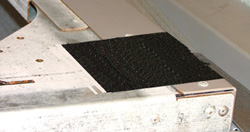
- Install four black adhesive labels (252-16277A) over the four holes
located on each corner of the multi-cassette autoloader. The holes are
accessable when the top covers are removed.
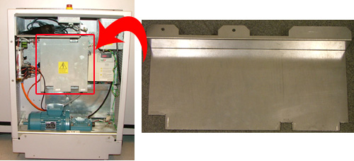
- Install the the multi-cassette unit E-box cover (252-13724A-51) over
the existing internal E-box cover.
- Remove the two screws securing the original internal cover.
- Install the supplied cover (252-13724A-51).
- Secure the supplied cover with the two screws removed in step
3a.
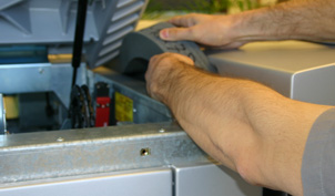
- To prevent plates from being exposed to external light, wedge a piece
of foam (252-16278A) into the gap formed between the multi-cassette
unit and the autoloader.
- Install the Velcro® fasteners and Light Tight covers
onto the multi-cassette autoloader, as described below:
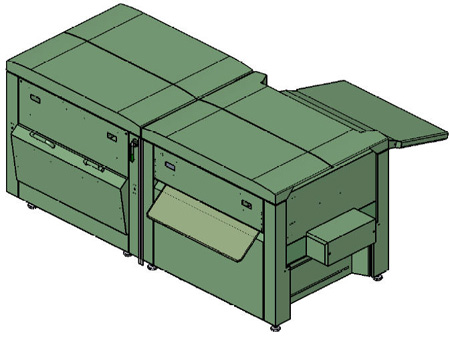
Front of multi-cassette autoloader
Rear of multi-cassette autoloader 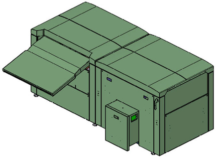
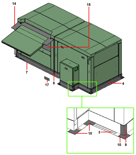
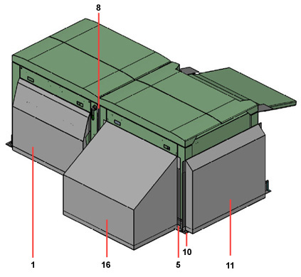
Applying the Velcro fasteners
Velcro fasteners are comprised of two layers: a hook layer, which
is a piece of fabric covered with tiny plastic hooks, and a loop
layer, which is covered with even smaller and hairier plastic loops.
- For each of the Light Tight kit covers, separate the strip of Velcro
loop layer from the hook layer.
Note: The hook layer is sewn into the Light
Tight kit covers.
- Use a cloth, dampened in isopropyl alcohol, to clean all the surface
areas of the multi-cassette autoloader where the strips are to be installed.
- When installing the Velcro strips onto the multi-cassette autoloader,
press hard on the back of the strips to ensure that they stick securely
to the device.
| MCU motor cover—252-16744A |
|
Installation notes:
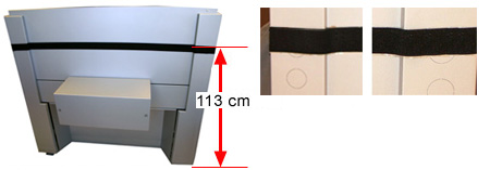
- Install the top of horizontal Velcro strip at a height of 113
cm from the floor.
- Fold the horizontal Velcro strip around the indentations on
the autoloader.
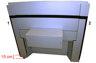
- Install the two vertical Velcro strips at a height of 15 cm
from the floor.
- Install the MCU motor cover (252-16744A) onto the multi-cassette
unit. Make sure that the bottom of the cover extends over the
floor to completely block out any light. It is imperative that
no light can enter through any gaps between the covers and the
floor.
|
Images:
|
Back to top
| Paper disposal side cover—252-15655A |
|
Installation notes:
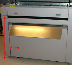
- Install the top of the horizontal Velcro strip at a height of
113 cm from the floor.
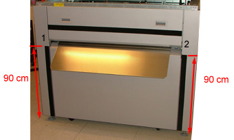
- Install the two vertical Velcro strips at a height of 90 cm
from the floor.
- Install the paper disposal side cover (252-15655A) onto the
autoloader. Make sure that the bottom of the cover extends over
the floor.
|
Images:
  |
Back to top
| User door cover—252-16279A |
|
Installation notes:
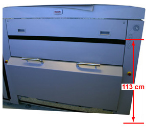
- Install the top of the horizontal Velcro strip at a height of
113 cm from the floor.
- Install the user door cover (252-16279A) onto the multi-cassette
unit. Make sure that the bottom of the cover extends over the
floor.
|
Images:
|
Back to top
| Vertical strip—252-16286A |
|
Installation notes:
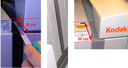
- Install the two vertical Velcro strips onto the front and rear
side of the multi-cassette autoloader panel.
- Leave enough excess strip (20 cm) to cover the top of the side
panel.
- Install the two vertical strip covers (252-16286A) onto the
front and rear side of the autoloader panel. Leave enough excess
cover (20 cm) to cover the top of the side panel.
|
Images:
|
Back to top
| Loading conveyor upper cover—252-15658A |
|
Installation notes:
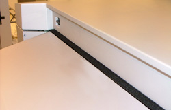
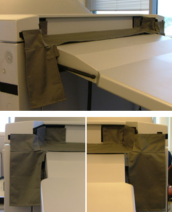
- Install the long horizontal Velcro strip onto the upper side
of the loading conveyor.
- Install the remaining Velcro strips onto the upper side of the
laoding conveyor.
- Install the loading conveyor upper cover (252-15658A) onto the
upper side of the loading conveyor. Align the cover with the horizontal
Velcro strip.
|
Images:
|
Back to top
| Loading conveyor lower cover—252-15659A |
|
Installation notes:
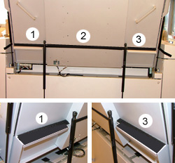
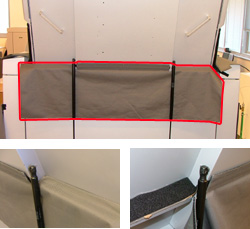
- Install the three horizontal Velcro strips onto the underside
of the loading conveyor.
- Install the loading conveyor lower cover (252-15659A) onto the
autoloader.
|
Images:
|
Back to top
Multi-cassette autoloader skirting
cover
Part numbers: 252-16280A/1A/2A/3A/4A/5A |
|
Installation notes:
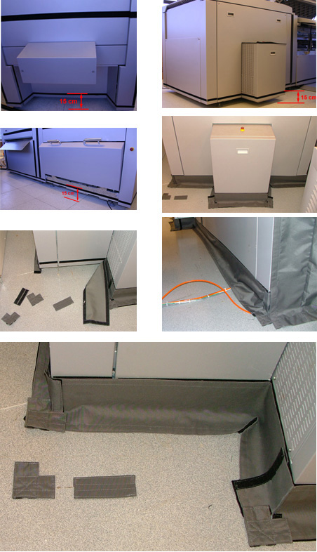
- Install the Velcro strips at a height of 15 cm from the floor.
- Install the lower covers (252-16280A,252-16281A, 252-16282A,
252-16283A, 252-16284A, 252-16285A) around the perimeter of the
multi-cassette autoloader.
- Install the corner connector covers (252-16696A, 252-16697A)
onto the corners of the multi-cassette autoloader.
|
Images:
|
Back to top
|

