Procedure |
|
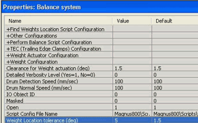
- In the Hardware Tree, locate the Properties: Balance system/Weight
Location tolerance (deg) parameter.
Amend the value of the parameter from 1.5 to 5.
- In Magnus Controller, click Raise Platform
to raise the platesetter loading platform.
- Remove the upper front panel.
There are two dynamic balance weights on the right side of the platesetter
and two dynamic balance weights on the left side of the platesetter.
The following steps ensure that the dynamic balance weights on each side
of the platesetter are located at 0° and 180° respectively.
Important: Perform steps
3-4 on the right side of the platesetter and then repeat the steps on
the left side of the platesetter.
- Drag one of the two dynamic balance weights to approximately 0°.
- Install the appropriate dynamic balance jig onto the platesetter.
Note: The right dynamic
balance jig is the thinner of the two dynamic balance jigs.
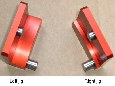
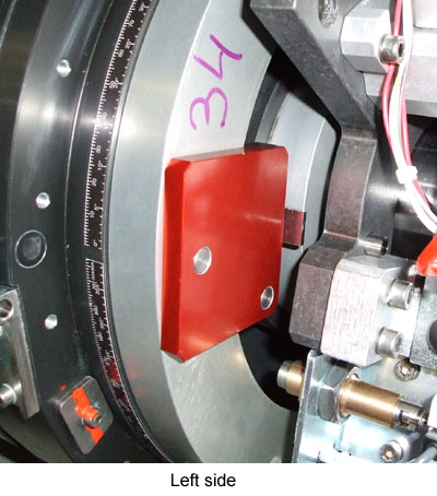
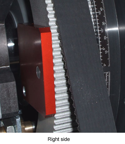
Install the right dynamic balance jig onto the right side of the platesetter,
and the left dynamic balance jig onto the left side of the platesetter.
- Each dynamic balance jig has two pins—A long pin and a short
pin. Insert the short pin into the drum pulley hole that is located
at 0°.
- Insert the long pin into the groove located on the dynamic balance
weight.
Note: The dynamic
balance weight may have to be moved slightly to accommodate the
pin.
- Drag the second dynamic balance weight to approximately 180°.
- Install the appropriate dynamic balance jig onto the platesetter
(left jig on left side, right jig on right side).
- Insert the short pin on the jig into the drum pulley hole that
is located at 180°.
- Insert the long pin on the jig into the groove located on the
dynamic balance weight.
Note: The dynamic
balance weight may have to be moved slightly to accommodate the
pin.
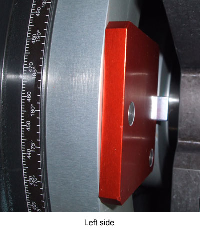
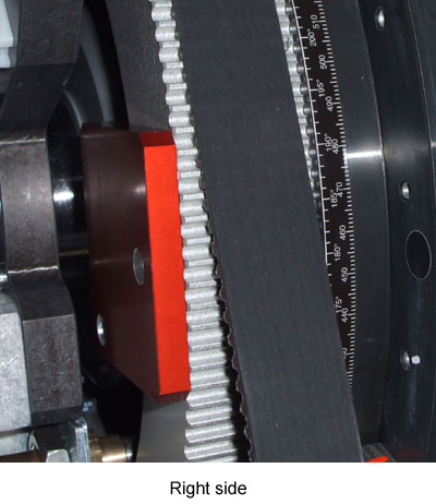
- Remove the dynamic balance jigs.
- In the Hardware Tree, locate and then click the Balance system parameter
(Software systems/Balance system)
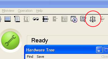
Note: The Balance system
can also be accessed in Magnus Controller by via the balance
system icon:
- Click Find Weights Location.
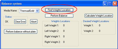
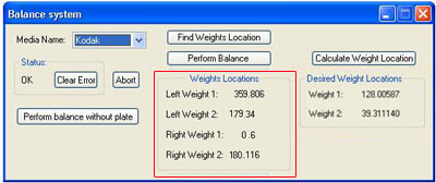
The Weights Locations area displays the location of
the four dynamic balance weights:
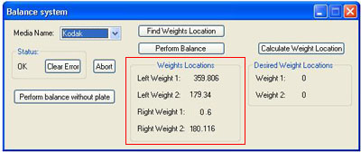
- Write down the locations of the left/right dynamic balance weights
that are closest to 0°.
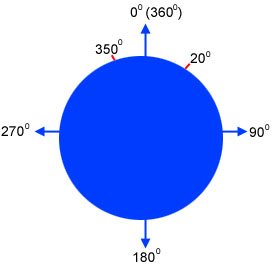
Note: As there are 360°
on a circle’s circumference, a weight located at 350° is closer
to 0° than a weight located at 20°:
- Calculate the average distance of the left and
right dynamic balance weights from their present location to 0°
(360°).
- If the location of the weight is between 180-360° then the
distance to 0° is a negative figure, and should be subtracted
from 360.
- If the location of the weight is between 0-180°, then the
distance to 0° is a positive figure and should be added to
0.
Example 1:
Left weight location = 358°
Right weight location = 357°
360 - 358 = -2
360 - 357 = -3
-2 + -3 = -5
Average location = -5 / 2 = -2.5
Example 2:
Left weight location = 3°
Right weight location = 1°
0 + 3 = 3
0 + 1 = 1
3 + 1 = 4
Average location = 4 / 2 = 2
- In the Hardware Tree:
- Locate the Balance system parameter (Software systems/Balance
system).
- Right-click the Balance system parameter and select Properties
from the list.
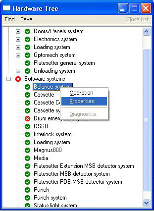
- The Properties: Balance system dialog box appears.
- Select the Weight Actuator Configuration parameter:
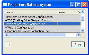
- Add or subtract the average dynamic weight
location to/from the existing Weight Actuator Configuration
value.
If the average dynamic weight is a negative number,
then subtract it from the existing Weight Actuator
Configuration value.
If the average dynamic weight is a positive number,
then add it to the existing Weight Actuator Configuration
value.
Example 1:
Weight Actuator Configuration value = 80
Average dynamic weight location = -2.5
Amend value to 80 - 2.5 = 77.5
Example 2:
Weight Actuator Configuration value = 80
Average dynamic weight location = 2
Amend value to 80 + 2 = 82
- In the Balance system dialog box, click Find Weights Location.
Verify that the maximum deviation between the average (left/right) weight
locations is ±1°. If the deviation is greater/smaller than
1°, then repeat steps 6-10.
- In the Balance system dialog box, select a media from the Media
list with the following attributes:
770 x 1030 x 0.3.
Note: If there is no media
available with these attributes, create one in the media tool, and then
access it from the Media list.
- In the Balance system dialog box, click Calculate Weight Location.
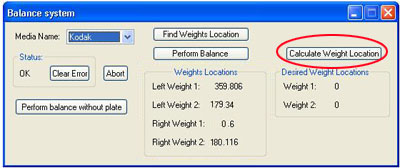
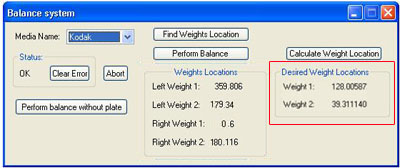
The calculated weight locations appear in the Desired Weight
Locations area. Make a note of the Weight 1
and Weight 2 locations.
- Click Perform Balance.
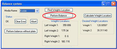
The platesetter performs a dynamic weight balance sequence. When the
sequence has been completed, the actual locations of all four weights
appears in the Weights Locations area. Make a note
of the weights’ locations.
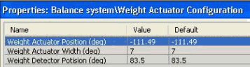
- Add or subtract the difference between the calculated weight location
(see step 12) and the actual weight location (see step 13), and then
update the following parameter’s value accordingly: Properties:
Balance system\Weight Actuator Configuration\Weight Actuator Position
(deg).
Example 1:
Actual position is less than the calculated position:
Calculated value = 90
Actual value = 88
Weight actuator position = 112
112 - (90 - 88) = 110
Amend value of weight actuator position to 110
Example 2:
Actual position is greater than the calculated position:
Calculated value = 90
Actual value = 92
Weight actuator position = 112
112 + (92 - 90) = 114
Amend value of weight actuator position to 114
- Perform the balance sequence again. Ensure that the balance weight
readings are within ±1°.
- In the Hardware Tree, locate the Properties: Balance system/Weight
Location tolerance (deg) parameter.
Amend the value of the parameter from 5 to 1.5.
|

