Procedure |
|
Workflow
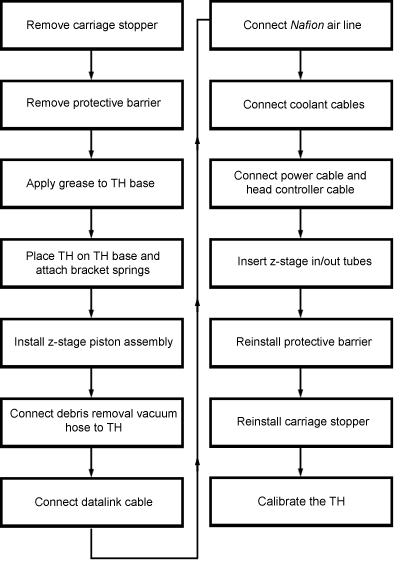
Preparing the head and carriage
- Remove the carriage stopper.
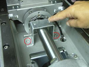
- Remove the protective barrier.
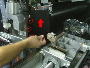
- Manually rotate the carriage until the thermal head base is at its
closest possible position to the right side door. When installing the
z-stage piston assembly, it is important to gain as much access as possible
to the thermal head base.
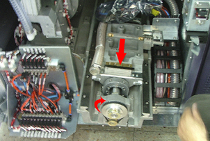
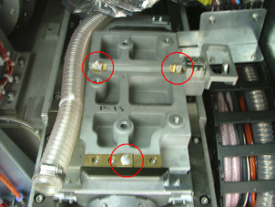
- Apply NSK Grease P2 to three specific locations
on the thermal head base, as depicted in the following image.
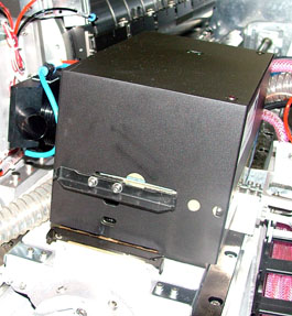
- Place the thermal head onto the thermal head base.
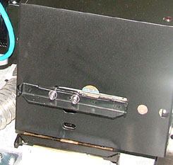
- Attach the four bracket springs from the head brackets to the carriage.
Installing the Z-stage piston assembly
The z-stage piston assembly secures the thermal head to the carriage.
- Use a flat-head screwdriver to remove the clip from the end of the
z-stage piston assembly.
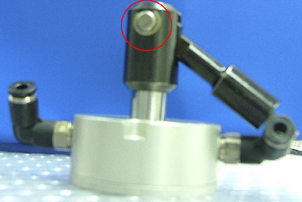
- Remove the pin securing the shaft to the z-stage piston assembly.
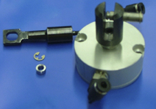
- Place the spacer on the end of the z-stage shaft.
Note: There are two types
of spacers:
- 252-00206A Z DISK QNTM 0.2 - 0.3
- 252-00207A Z DISK QUANTUM 0.15 TO 0.4
Use the spacers that are relevant to the customer’s media.
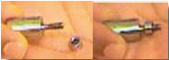
- Insert the shaft through the z-stage block, spacer-end first.
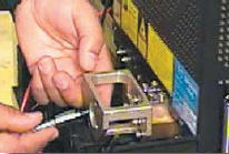
- Align the shaft so that the hole on the end of the shaft is horizontal.
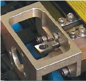
- Insert a hex key through the hole (on the end of the shaft), and tighten
the shaft by rotating the hex key. The shaft secures the thermal head
to the carriage.
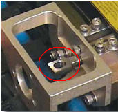
- Insert the pneumatic cylinder onto the end of the shaft. Use the pin
(removed in step 2), to secure the pneumatic cylinder to the shaft.
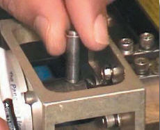
- Insert the clip (removed in step 1), onto the end of pin.
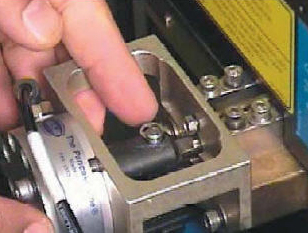
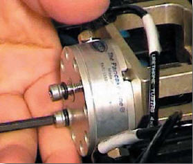
- Use a 4-mm hex key and two screws to secure the pneumatic cylinder
to the z-stage block.
Wiring the thermal head
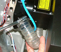
- Connect the debris removal vacuum hose to the thermal head. Make sure
to tighten the screw on the clamp.
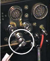
- Connect the data link cable to the thermal head.
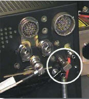
- Connect the Nafion air line to the thermal head.
- Remove the orange protective covers from the ends of the two coolant
cables.
- Connect the two coolant cables to the thermal head.
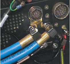
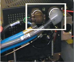
- Connect the power cable and the head controller cable to the thermal
head.
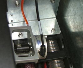
- Insert the black z-stage in tube, and the orange
z-stage out tube into the relevant connectors on the
z-stage pneumatic cylinder.
Note: The black z-stage
in tube’s connector is located closer to the right side door than
the z-stage out connector.
- Manually rotate the carriage until there is sufficient room to reinstall
the protective barrier to the optomech assembly.
- Use a 4-mm hex key and three screws to reinstall the protective barrier
to the optomech assembly. Apply Loctite 242 adhesive to the screw
threads.
- Use a 4-mm hex key and two screws to reinstall the carriage stopper
to the optomech.
Calibrating the thermal head
Warning: When zeroing the
focus error, make sure your eyes are directed either below, or at the
same height as, or to the left of the laser protective barrier.
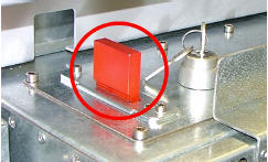
- Insert the red bypass key into the bypass switch.
- Load a plate onto the drum via the Magnus 800 Controller software.
- Set the correct media by typing:
Magnus >> media<media number>, followed by
Magnus >> set media <enter media number>
- Slightly loosen the four screws securing the z-stage.
- Type:
Magnus >> zstage forward
- From the Magnus 800 Controller software, move the carriage to position
150 mm and ensure it is over the plate, alternatively, from Service
Shell, type:
Magnus >> carriage moveto 150
- From the Magnus 800 Controller software, move the drum to position
140, or alternatively, from Splot type:
Magnus >> drum move 140
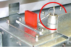
- Insert the focus laser bypass key into the focus laser bypass switch
and rotate the key.
- Type:
Magnus >>head install on
The state, sum, and error parameter results will be displayed.
- Use a 7-mm open wrench to set the focus error according to the Z-stage
unit fix spacer table.
To set the error, either tighten or loosen the adjusting screw on the
z-stage unit.
Note: If the error = 50
in both positions of the z-stage (forward and backwards), then
the head is not positioned in front of the plate.
The sum parameter should be approximately 1200+/- 300.
Note: The sum is affected
by the reflectivity and the rcvgain parameters (Do not change).
If the sum is greater than 1200, increase the reflectivity; if it is
less than 1200,
decrease the reflectivity.
- Tighten the four screws securing the z-stage.
- Type:
Magnus >>zstage back. Check the error adjustment.
the error
should be approximately 0 for 0.3 mm plates.
- Type:
Magnus >> head install off
|

