|
Product |
|
Kodak Magnus 800 platesetter
|
|
Background |
|
If the trailing edge clamp (TEC) actuator beam is neither parallel to
the drum nor set to the optimum height, it may cause TEC-related problems
and loading failures.
This procedure describes how to ensure that the TEC actuator beam is correctly
positioned in relation to the drum.
|
|
Requirements |
|
TEC actuator parallel adjustment jig (690-00771A)
Note: The jig is included
in the Magnus 800 personal jig kit
(516-00021A).
|
|
Procedure |
|
Check the height of the TEC actuator beam
- Make sure all the TECs are located on the actual drum and not on the
TEC actuator beam.
- Manually rotate the drum until the TECs are positioned as far away
as possible from the TEC actuator beam.
- Remove the two brackets that protect the magnetic sensors. Each bracket
is secured to the TEC actuator beam with four screws.
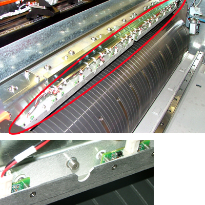
- Lower the TEC actuator beam.
- Insert the bypass key.
- In Kodak Magnus Controller, use the TEC actuator valve
to lower the TEC actuator beam toward the drum.
- In Magnus Controller, make sure the TEC actuator horizontal
cylinder’s status is off. This ensures that the TEC actuator
lever pusher is located in its lower position.
- To ensure that the TEC actuator beam is correctly positioned, use
the TEC actuator parallel adjustment jig (690-00771A).
A hole is located on one end of the jig. This is referred to as the
no-go end of the jig. The other end of the jig (the end without
the hole) is referred to as the go end of the jig.
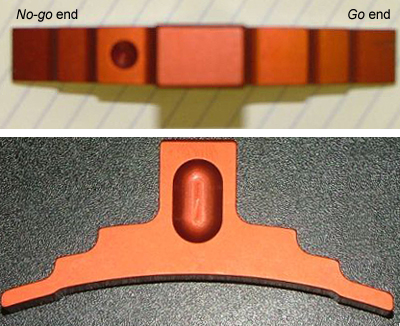
- The go end of the jig is slightly thinner than the no-go
end of the jig.
- The thickness differential between the jig ends represents the
height tolerance range of the TEC actuator beam in relation to the
drum.
- The optimum minimum height of the TEC actuator beam is achieved
when you can smoothly insert the go end of the jig in between
the surface of the drum and the underside of the TEC actuator lever
pusher. Ideally, there should be a minimum amount of friction against
the jig.
- The optimum maximum height of the TEC actuator beam is achieved
when there is not enough clearance to insert the no-go end
of the jig in between the surface of the drum and the underside
of the TEC actuator lever pusher.
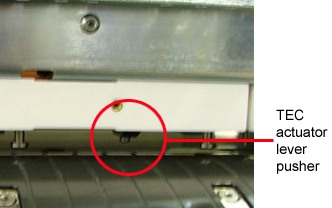
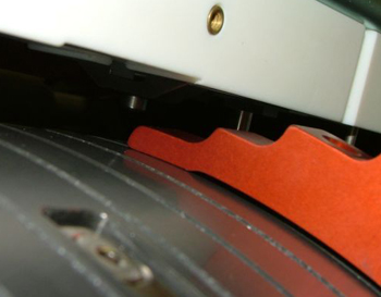
- Insert the go end of the jig in between the surface of the
drum and the left underside of the TEC actuator lever pusher. If there
is too much resistance against the jig, or if you can easily insert
the jig, adjust the height of the TEC actuator cylinders according to
the table below.
Repeat this step on the right underside of the TEC actuator lever pusher.
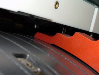
- Try to insert the no-go end of the jig in between the surface
of the drum and the left underside of the TEC actuator lever pusher.
If you can insert the jig into the gap, adjust the height of the TEC
actuator cylinders according to the table below.
Repeat this step on the right underside of the TEC actuator lever pusher.
Adjust the height of the TEC actuator beam
| If |
Do This |
| You cannot insert the go end of the jig between the surface
of the drum and the TEC actuator lever pusher. |
Raise the height of the TEC actuator cylinders. |
| The go end of the jig can be inserted too easily between
the surface of the drum and the TEC actuator lever pusher. |
Lower the height of the TEC actuator cylinders. |
| You can insert the no-go end of the jig between the surface
of the drum and the TEC actuator lever pusher. |
Lower the height of the TEC actuator cylinders. |
- Remove the four screws that secure the TEC actuator cylinder.
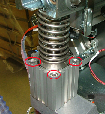
- Take one of the following actions:
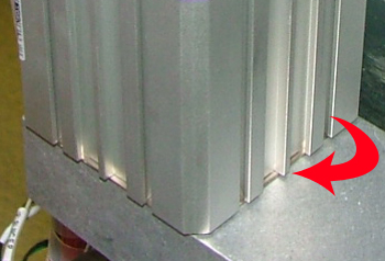
- Raise the height of the TEC actuator beam by inserting shims under
the TEC actuator cylinder.
- Lower the height of the TEC actuator beam by removing the shims
under the TEC actuator cylinder.
Note: There are two
types of shims—0.5 mm (25-06769A) and 1 mm (252-06768A).
Both types of shims are included in the Magnus 800 personal parts
kit (518-01794A).
- Reinstall the four screws that secure the TEC actuator cylinder.
|
|
Test |
|
- Insert the go end and no-go end of the jig in between
the surface of the drum and the TEC actuator lever pusher.
- Make sure the TEC actuator beam is positioned at the optimum height.
- Load and unload several of the customer’s plates.
|
|
Technical contact(s) |
|
Content owner: Yaron Shifman
See the Escalation page for escalation
contacts.
|
Date submitted |
|
04 Oct 2006
|

