Home | Contact Us | Submit Troubleshooting Info | Search | Help


    Output | Software Solutions | Proofing | Color, Screening and Calibration | Scanning | Digital Photography | Consumables | POS


Sequence and parameter reference guide for the Magnus 800 platesetter

This reference guide describes the sequences and parameters for the Kodak® Magnus™ 800 platesetter.

See also:

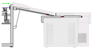
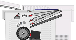
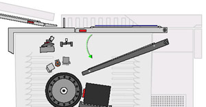
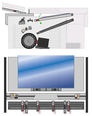
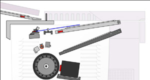
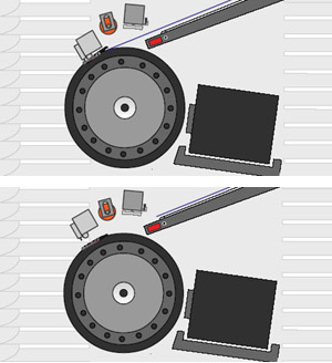
Autoloader to loading conveyor

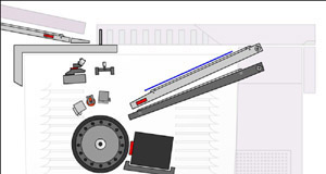
Sequence 1: Plate moves from autoloader to loading conveyor.
Parameter:
  • Loading conveyor plate receiving speed 140 mm/sec
  • Exit rollers plate receiving speed 20 mm/sec
  • Plate picker to plate transfering to exit roller:target position -14 mm
  • Plate picker to plate transfering to exit roller: speed 10 mm/sec


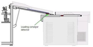
Seq. 2: Plate is detected by loading conveyor detector.
Parameter:

Max waiting time for plate to cover loading conveyor detector 14000 msec


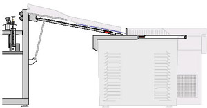
Seq. 3: Plate aligns with shutter.
Note: When implementing bypass loading, the operator must align the plate according to the label on the shutter.
Parameter: Loading conveyor plate aligning speed 75 mm/sec
(The plate moves in a lower speed in order to align the plate to the shutter)


Loading platform to loading conveyor

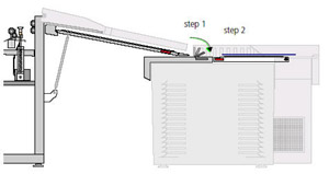
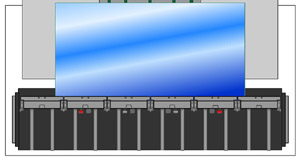
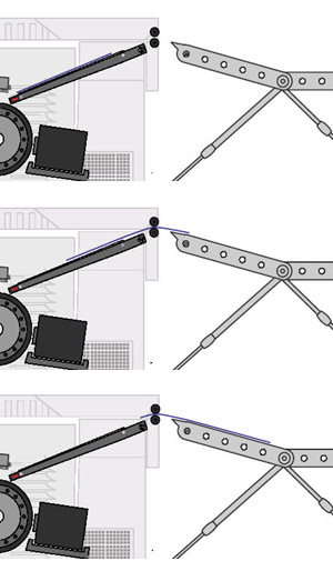
Seq. 4: Shutter opens and the plate moves toward the loading platform. The plate then crosses the loading platform front detector. In this sequence the shutter (piston), loading platform, and loading conveyor are all working.
Parameter:
  • Loading plarform motor plate receiving speed 250 mm/sec
  • Loading conveyor plate transfering speed 250 mm/sec


Seq. 5: Plate is on the loading platform.
Parameter:  


Plate alignment and punch process

Seq. 6: Plate is waiting on the loading platform.
Parameter:  

Seq. 7: Loading platform short cylinders move the loading platform towards the punch and alignment system. The fixed pin and the spring pins are moving to the preposition.
Parameter:  

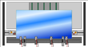
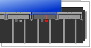
Seq. 8: Plate moves towards the punch and alignment system. It stops when reaching the registration pins (located inside the holder). A short should be created between the two registration pins in order to move to the next step. In case a plate is attached to the registration pin an automatic machine retry will occur.
Note: The loading platform belt is constantly moving during this stage.
Parameter:
  • Max time for plate to touch punch registration pins 10000 msec
  • Loading plarform motor plate alignment speed 150 mm/sec (belt speed)
  • Loading plarform motor revese for retry travel 1000 mm (only when retry - plate moving back)


Seq. 9:
  1. The plate is attached to the registration pins.
  2. The plate width measurement process starts.

Note:

  1. Fixed pin and spring pins optic detectors should appear as off (not detect the plate) in order to start the measurement.
  2. Go detector process to fixed pin and spring pins starts.
  3. The script calculates the plate width.
Parameter:

The script calculation for the fixed pin and spring pins preposition:

  • Set dSpringPinPrePos = (SpringHPDistanceToCenter - (m_dMediaToLoadMaxHSize_mm/2) - DistanceSpringWaitPosAndPlateAdge)
  • Set dFixPinPrePos = (FixHPDistanceToCenter - (m_dMediaToLoadMaxHSize_mm/2) - DistanceFixWaitPosAndPlateAdge)

Parameter for spring and fix pin speed for measurement:

  • Fix pins plate detection speed 10 mm/sec
  • Spring pins plate detection speed 15 mm/sec


Seq. 10:

Aligning the plate for the punch process.

The alignment sequence starts depending on the plate current location on the loading platform:
If plate is aligned to the left (spring pin side):

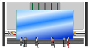
  1. Fixed pin moves to out point.
  2. Spring pin moves to In point - the spring pin pushes the plate until the plate reaches the fixed pin optic detector.
  3. Spring pin moves to its final point.
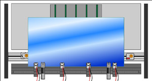
  4. Fixed pin starts moving the plate to its final point.

If plate is aligned to the right (fix pin side):

  1. Spring pin moves to its final point.
  2. Fixed pin starts moving the plate to its final point.
Parameter:

Spring and fixed pins plate alignment speed:

  • Spring and Fix pins Normal speed 20 mm/sec (stage 1 output)
  • Spring pin positioning speed 3 mm/sec (stage 2 intput)
  • Spring pin positioning speed 3 mm/sec (stage 3 spring final point)
  • Fix pin positioning speed 3 mm/sec (stage 4 fix final point)


Plate punching process

Seq. 11:
  1. Holders mechanism holds the plate and the punch process start.
  2. The fixed and spring pins move to the preposition before punching the plate.
  3. Plate moves back to the loading platform after the punch is done.

Note:

  1. Before holders hold the plate the system verifies that there are still good attachment to the registration pins.
  2. Plate moves back to the loading platform - the plate reverse movement is until the loading platform front detector reads off.
Parameter:


From punch position to drum position

Seq. 12:
  1. The loading platform moves to pre-drum position in case there is already a plate on the drum.
  2. The plate is waiting on the loading platform until the plate on the drum is unloaded.

Note: There are no detectors for this loading platform position.

Parameter:


Seq. 13:

The loading platform moves to drum position. The plate is waiting on the loading platform until the plate on the drum is unloaded. Before loading the plate - the balance process starts (required only when the plate size is new).

Parameter:


From loading platform to drum

Seq. 14:
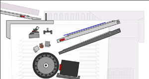
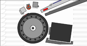
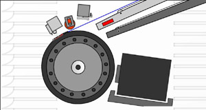
  1. The drum rotates to the LEC position to load the plate.
  2. LEC actuator opens the LEC clamps to catch the plate.
Parameter:

Drum Position for LEC -664 mm (drum position for LEC)


Seq. 15:

The plate moves toward the LEC clamp and attaches to the registration drum pins.
This movement is divided into two speeds:

  • High speed - for short distances.
  • Low speed - for a smooth plate attachment to the registration drum pins.

In this stage, a short should be created between the registration pins. In case it does not happen, an automatic machine retry will occur.

Parameter:

Offset for plate width calculation 25 mm (short distance speed)

Loading platform motor loading plate to drum speed 350 mm/sec (plate attachment speed)

Max Plate Size For Small Drum Reg Pin 625 (checks whether a small plate or a large plate is attached to the registration pins on the drum)


Seq. 16:
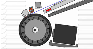
  1. The LEC clamps grip the plate, and the LEC Actuator rises up.
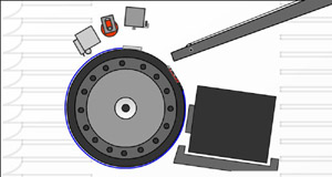
  2. The roller is moving down.
  3. The drum is ready to wrap the plate.
  4. The vacuum pump starts working.
Parameter:


Seq. 17:
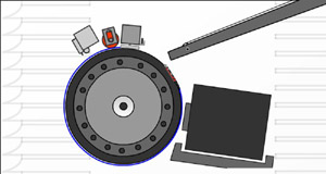
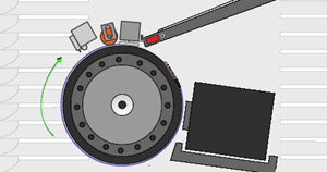
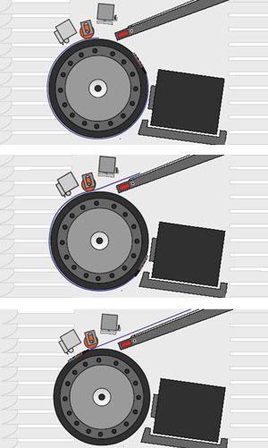
  1. The plate is wrapped around the drum.
  2. The roller irons the plate.
Parameter:
  • Drum wrapping speed 1500 mm/sec (drum wrapping speed)
  • Display plate size (around the drum) message 0 (to display the plate length during this sequence with pop-up message on the controller, you should set the parameter value to 1).

Seq. 18:

The TEC clamps attach the plate to the drum in the trailing side. This is the following TEC actuator sequence, under: Platesetter/Optomech/TEC system:

  1. TEC vertical actuator Valve - ON
  2. TEC pressure regulation - ON
  3. TEC Horizontal actuator valve - ON

In order to complete this stage all Mag_sensors should appear as off (LED off). There is an option to mask each Mag_sensor.
Note: Be careful when masking these sensors.

Parameter:


Seq. 19:
  1. The plate is attached to the drum and is ready to be exposed.
  2. The loading platform moves to preposition to receive a new plate.
Parameter:


Unloading plate from drum

Seq. 20:
  1. The drum moves to the TEC position.
  2. The roller is moving down.
  3. The TEC actuator removes the TEC clamps from the drum.
  4. The unloading platform belts start rotating.

Verify that the TEC Horizontal actuator valve is switched to off (end position) before you are lowering the TEC Actuator. All the Mag_sensors have to read on after grabbing the clamps from the drum in order to continue the process.
Note: Be careful when masking these sensors.

Parameter:

Unloading plarform motor plate Receive speed 250 mm/sec (Unload belt rotation speed)


Seq. 21:
  1. The drum starts rotating to the unloading direction, until it reaches the LEC position.
  2. Near detector on the Unloading Platform detects the plate (reads on).

The Unloading platform detector has two positions:

  1. Lower position - the leading plate edge reaches the unloading platform.
  2. Upper position - for increasing the plate friction with the belt during the unloading process. (You can control this position).
Parameter:
  • Max time for plate to cover Unloading platform near drum detector 5000 msec (time out)
  • Max Plate Size (around the drum) To Actuate Unloading platform 1500 mm (maximum plate size)

Seq. 22:
  1. The drum roller is moving up.
  2. The LEC actuator opens the clamps (going down).
  3. The near drum detector should read off - the plate completely covers the unloading platform.
  4. The unloading platform belts stop rotating (when the near drum detector reads off).

After the plate completely covers the unloading platform, the LEC clamps are still open in order to receive the next plate.

Parameter:

Max time for plate to discover Unloading platform near drum detector 10000 msec (time out)


Plate moves to Unload Conveyor

Seq. 23:
  1. The unloading platform will eject the plate after verifying the following:
    1. There is no Kodak unloading Conveyor placed, the machine verifies that the processor is ready to accept the plate.
    2. The unloading conveyor is empty and ready.
  2. The unloading conveyor belts start rotating.
  3. The unloading platform belts start rotating.
  4. The plate covers the exit detector - reads On.
  5. The plate stops covering the unloading platform exit detector - reads Off.
Parameter:
  • Unloading plarform motor plate Transfer speed 150 mm/sec (unloading platform speed)
  • Unloading Conveyor motor plate receiving speed 105 mm/sec (unloading conveyor speed)
  • Max time for plate to cover Unloading platform exit detector 10000 msec (time out)
  • Max time for plate to discover Unloading platform exit detector 10000 msec (time out)


    Copyright © 2005 Creo Inc. All rights reserved. Confidential. Back to top.