Procedure |
|
This procedure describes how to verify the position of the following:
Front top cover
Make sure the front top cover is correctly positioned in relation
to the autoloader chassis
- Make sure the Kodak Magnus 800 autoloader is level.
- Raise the autoloader front top cover.
- Release, but do not remove, the four screws securing each of the two
front top cover latches.
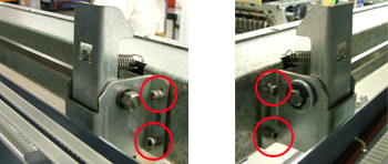
- Place 7 mm of feeler gauges on the front top-left
side and front top-right side of the autoloader chassis.
- Close the front top cover until it touches both sets of feeler gauges.
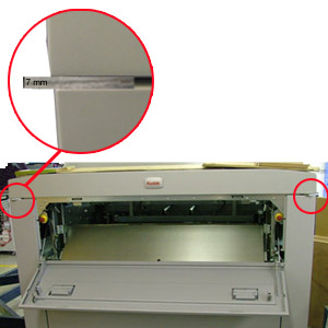
Important: The depth of
the feeler gauges may prevent the latches from securing the front top
cover in a closed position; therefore, if required, ask an engineer
to place pressure on the front top cover to secure it in position.
- From inside the autoloader, adjust the height of the latches until
they firmly secure the front top cover.
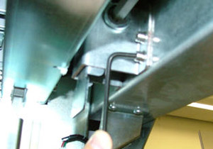
- When the latches are in their optimum position, retighten the screws.
Verify the depth of the top cover safety
switch key
Important: This procedure
is applicable to both the front and rear top cover safety switches and
their safety switch keys.
Perform this procedure on the front top cover, and when
instructed to do so, perform the same procedure on the rear top cover.
Verify that the cover safety switch key enters the safety switch at the
correct depth (approximately 3 mm). If a safety switch key does not enter
deep enough inside the safety switch, then the safety switch may function
erratically.
- In the Hardware Tree, locate the relevant top cover open detector
dialog box.
- Open the top cover but do not remove the 7 mm of
feeler gauges.
- Slightly release, but do not remove, the screws securing the top cover
safety switch.
Important: Do not release
the screws too much, otherwise the safety switch bracket may slide too
far out of position.
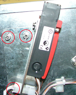
- Place an additional 4 mm of feeler gauges onto the existing 7 mm of
feeler gauges. There should be a total of 11 mm of feeler gauges on
the top-left side and top-right side of the autoloader chassis.
- Close the top cover, and in the relevant top cover open detector dialog
box, make sure the status is off.
Important: If the status
is on, lower the height of the safety switch until its status reverts
to off.
- Remove a 1-mm feeler gauge from both sets of feeler gauges. There
should be a total of 10 mm of feeler gauges on the top-left side and
top-right side of the autoloader chassis.
- Check the status of the detector.
- If the status of the detector reverts from off to on, proceed
to step 8.
- If the status of the detector remains off, slightly raise the
height of the safety switch until the status of the detector reverts
to on.
- Open the top cover and retighten the screws securing the top cover
safety switch.
Rear top cover
Make sure the rear top cover is correctly positioned in relation
to the autoloader chassis
- Raise the autoloader rear top cover.
- Release, but do not remove, the two screws securing each of the two
rear top cover latch holders.
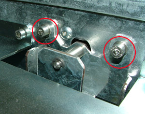
- Place 7 mm of feeler gauges on the rear top-left
side and rear top-right side of the autoloader chassis.
- Close the rear top cover until it touches both sets of feeler gauges.
Important: The depth of
the feeler gauges may prevent the latches from securing the rear top
cover in a closed position; therefore, if required, ask an engineer
to place pressure on the rear top cover to secure it in position.
- From inside the autoloader, adjust the height of the latch holders
until they firmly secure the rear top cover.
- When the latch holders are in their optimum position, retighten their
screws.
Make sure the rear top cover latches are aligned with the latch
holders
When lowering the rear top cover, centrally align the diagonal side of the
latch with the latch holder.
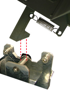
Adjust the angle of each latch by adjusting the length of the latch stopper
screws.
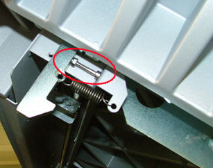
Verify that the safety switch key,
on the rear top cover, is aligned to the rear top cover safety switch
Verify that the safety switch key, on the rear top cover, enters the
safety switch at the correct depth (approximately 3 mm). If a safety switch
key does not enter deep enough inside the safety switch, then the safety
switch may function erratically.
- In the Hardware Tree, locate the relevant rear top cover open detector
dialog box.
- To verify whether the safety switch key enters the safety switch at
the correct depth, repeat the same procedure on
the rear top cover as that used for verifying the depth of the front
top cover safety switch key.
Paper disposal door
Verify that the safety switch key on the paper disposal door is aligned
to the paper disposal door safety switch.
- Open the paper disposal door.
- Place a strip of masking tape over the safety switch’s entry
point.
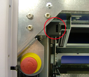
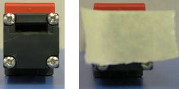
- Close the paper disposal door just enough for the safety switch key
to punch holes in the masking tape, and then reopen the door.
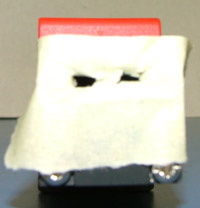
- Verify that the punched holes on the masking tape (created by the
safety switch key) are located in the center of the safety switch’s
entry point.
If the punched holes are not centered, adjust the position of the safety
switch.
- Loosen the three screws securing the safety switch.
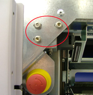
- Adjust the position of the safety switch.
- Retighten the three screws.
Important: On multi-cassette
autoloaders, verify the position of the service panel.
|

