Procedure |
|
Make sure the autoloader runners are of equal heights
There are two sets of autoloader runners - a set at the front of the
autoloader, and a set at the rear of the autoloader. This step describes
how to adjust the two sets of autoloader runners to ensure that they of
equal height to one another.
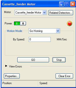
- In Magnus Controller, locate the Cassette_feeder Motor dialog
box, and send the cassette feeder to home position.
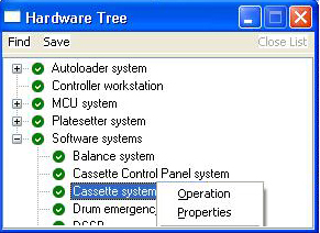
- From the Hardware Tree, under Software systems, right-click
Cassette system and select Properties.
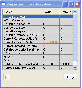
- In the Properties: Cassette system dialog box, double-click MCU
Parameters.
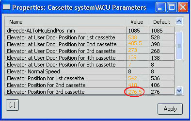
- In the Properties: Cassette system\MCU Parameters
dialog box, note the value for the Elevator Position for 3rd
cassette parameter.
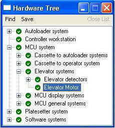
- From the Hardware Tree, locate, and then double-click Elevator
Motor (MCU system > Elevator systems > Elevator Motor).
- In Magnus Controller, make sure the Cassette Feeder and Cassette
Locker valve status is on.
- In the Elevator Motor dialog box, perform the following actions:
- In the Motion Mode list, select Go To
Position.
- In the Position box, type the value
of the elevator position for third cassette.
- In the Speed box, type 8.
- Click GO.
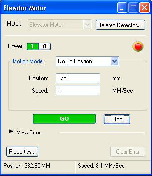
The elevator moves the third cassette to the autoloader entrance.
- Use the adjusting jig to compare the heights between the autoloader
runners and the MCU runners.
- Place the long edge of the adjusting jig onto the autoloader’s
front runners.
- Slide the adjusting jig from the autoloader front runners to the
MCU front runners.
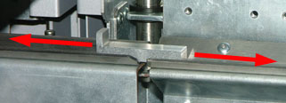
- Estimate the height difference between the autoloader front runners
and the MCU front runners.
- Place the adjusting jig on the autoloader’s rear runners,
and then slide the jig from the rear runners to the MCU’s rear
runners.
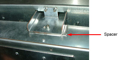
- If the autoloader’s front runners are at a different height
to the autoloader’s rear runners, then add/subtract spacers
(252-07396A) to one set of autoloader runners.
- Use the adjusting jig to test the height amendment and make sure the
autoloader’s front runners are at the same height as the autoloader’s
rear runners.
Aligning the MCU runners to the autoloader runners
This step describes how to align the height of the MCU runners to the
height of the autoloader runners.
Note: In the previous step,
(Make sure the autoloader runners are of equal heights), cassette number
three is used to determine the height differential between the autoloader
runners.
Cassette number three, is therefore located closer to the autoloader level
than any other cassette; and as such, when aligning the MCU runners to
their autoloader levels, it is recommended to begin with cassette number
three.
- Use the adjusting jig to compare the difference in
height between cassette’s runners and the autoloader runners.
- Place the long edge of the adjusting jig onto the autoloader’s
front runners.
- Slide the adjusting jig from the autoloader’s front runners
to the MCU’s front runners.
- Make a note of the height difference.
- From the Hardware Tree, locate, and then double-click Elevator
Motor (MCU system > Elevator systems > Elevator Motor).
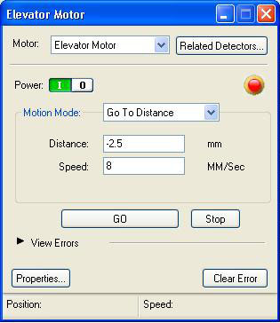
In the Elevator Motor dialog box, perform the following actions:
- In the Motion Mode list, select Go To
Distance.
- In the Distance box, type the difference in height
between the autoloader runners and the MCU runners.
- If the autoloader runners are lower than MCU runners, then
type the height difference as a positive number.
- If the autoloader runners are higher than the MCU runners,
type the height difference as a negative number.
- In the Speed box, type 8.
- Click GO.
- Use the adjusting jig and make sure the autoloader’s runners
are at the same height as the MCU’s runners.
If the heights are not equal, then perform the following actions:
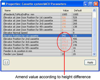
- Locate the Properties: Cassette system\MCU Parameters dialog box.
- Add/subtract the original difference in height
to/from the existing values for all the Elevator Position
for... cassette parameters and click Apply.
For example, if the height difference is -2.5 mm, then adjust all
the parameters’ values by -2.5.
- Make sure the MCU runners for the remaining four cassettes are correctly
aligned to the autoloader level. In the Hardware Tree, locate the Elevator
Motor dialog box, and perform the following actions:
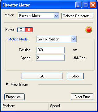
- In the Motion Mode list, select Go To
Position.
- In the Position box, type the autoloader level
associated to each individual cassette.
Important: The Registry
Values for each MCU may be slightly different than the values depicted
in this procedure. When calibrating the MCU, only refer to the values
denoted in the MCU Registry. Do not refer to the default values,
or the values in the table below.
|
Cassette Number
|
Autoloader Level*
|
|
1
|
542 mm
|
|
2
|
410 mm
|
|
3
|
276.5 mm
|
|
4
|
143.5 mm
|
|
5
|
10.5 mm
|
| *These
values are for indicative purposes only |
- In the Speed box, type 8.
- Click GO.
- Use the adjusting jig to compare the difference in height between
the autoloader runners and the MCU runners. If there are any height
differences, then amend the Elevator Position parameter for that specific
position.
For example, if the height difference is 1 mm, do the following:
- Locate the Properties: Cassette system\MCU Parameters dialog box.
- Add 1 to the existing Elevator Position parameter, and click Apply.
Aligning the MCU runners to the user door level
After the MCU runners have all been aligned to the autoloader level,
it is necessary to align all the runners to the user door level. This
step describes how to align the MCU runners to the user door level.
- In the Hardware Tree, locate the Elevator Motor dialog
box, and perform the following actions:
- In the Motion Mode list, select Go To
Position.
- In the Position box, type the approximate user
door level associated to each individual cassette.
Important: The Registry
Values for each MCU may be slightly different than the values depicted
in this iprocedure. When calibrating the MCU, only refer to the
values denoted in the MCU Registry. Do not refer to the Default
values, or the values in the table below.
|
Cassette Number
|
AUser Door Level*
|
|
1
|
538 mm
|
|
2
|
405.5 mm
|
|
3
|
273 mm
|
|
4
|
139 mm
|
|
5
|
7 mm
|
| *These
values are for indicative purposes only |
- In the Speed box, type 8.
- Click GO.
- Use the adjusting jig to make sure the MCU runners
are aligned to their user door level:
- Place the long edge of the adjusting jig onto the MCU runners.
- Slide the adjusting jig from the MCU runners to the user door
runners.
- Make a note of any height differences.
- If there are any differences between the heights, locate the Properties:
Cassette system\MCU Parameters dialog box, and add or subtract the
difference in height to or from the existing value for the Elevator
at User Door Position for... cassette parameter.
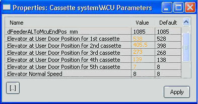
- Click Apply.
Note:
If the MCU runners are lower than the user door
runners, then type the height difference as a positive number.
If the MCU runners are lower than the user door runners, then type
the height difference as a negative number.
- Repeat steps 1 and 2 for all
MCU runners.
Checking the tolerance level of each cassette
This step describes how to check the tolerance level of each cassette.
The tolerance level must be set at a minimum of 3 mm (0.12 in.) in either
direction (up and down).
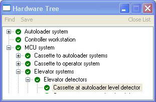
- From the Hardware Tree, locate and then double-click Cassette
at autoloader level detector (MCU system > Elevator systems
> Elevator detectors > Cassette at autoloader level detector).
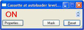
The Cassette at autoloader level detector dialog box appears.
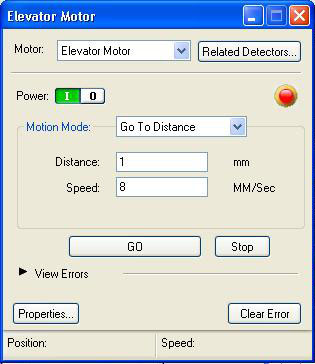
- From the Hardware Tree, locate, and then double-click Elevator
Motor (MCU system > Elevator systems > Elevator Motor).
In the Elevator Motor dialog box, raise and lower each cassette by 1
mm (0.04 in.).
- Check if the status of the cassette at autoloader level detector reverts
from ON to OFF. If the detector’s
status changes, then adjust the tolerance level of the detector, as
described in the step Adjusting the tolerance of the autoloader
level detector.
- In the Elevator Motor dialog box, raise and lower each cassette by
a further 1 mm (0.04 in.). Check if the status of the cassette at autoloader
level detector reverts from ON to OFF.
If the detector’s status changes, then adjust the tolerance level
of the detector, as described in the step , as described in the step
Adjusting the tolerance of the autoloader level detector.
- Raise and lower each cassette by a further 1 mm (0.04 in.) (3 mm /
0.12 in. in total) and make sure the cassette at autoloader level detector
reverts from ON to OFF. If the detector’s
status does not change, then adjust the tolerance level of the detector,
as described in the step Adjusting
the tolerance of the autoloader level detector.
Adjusting the tolerance of the autoloader level detector
This step describes how to adjust the tolerance level for the cassette
at autoloader level detector.
If the tolerance level for the cassette at autoloader level detector is
less than 3 mm (0.12 in.) in either direction (up or down), then perform
the following actions:
- Undo the two screws securing the SCU Level detector.
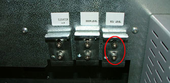
- Reposition the detector.
- In the Elevator Motor dialog box, lower and raise each cassette by
1 mm (0.04 in.), and make sure the detector’s status remains ON.
- Lower and raise each cassette by a further 1 mm (0.04 in.), and make
sure the detector’s status still remains ON.
- Lower and raise each cassette by a further 1 mm (0.04 in.) (3 mm /
0.12 in. in total), and make sure the detector’s status reverts
to OFF.
Checking the position of the cassette feeder
This step describes how to verify if the cassette feeder is correctly
positioned inside the autoloader.
- In the Hardware Tree, locate the Cassette system dialog box.
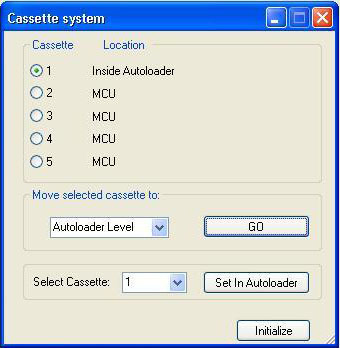
- In the dialog box, send a cassette from the MCU to the autoloader.
- In the Hardware Tree, locate the Plate picker motor dialog box, and
do the following:
- In the Motion Mode list, select Go To
Position.
- In the Position box, type 850.
- In the Speed box, type 150.
- Click GO.
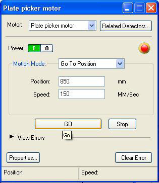
The plate picker moves towards the holes on the cassette tray.
- Check if the plate picker suction cups fall directly over the holes
on the cassette tray.
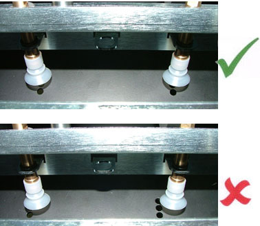
- If the suction cups and holes are not aligned, then perform the following
actions:
- In the Hardware Tree, double-click MCU parameters.
- Locate the Feeder in AL position in mm parameter.
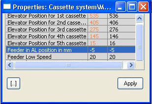
- Amend the value of the parameter. A lower value moves the feeder
further into the autoloader; a higher value moves the feeder a lesser
distance into the autoloader.
Note: In order for
the changes to take affect, restart Magnus Controller.
|

