Solution |
|
| Problem |
Solution |
| MCU timing belt is not meshing with the tension pulley’ teeth
and the MCU is unusable. |
Perform the following procedures in their entirety. |
| MCU runners are not parallel to the MCU floor. |
Perform the following procedures beginning from step
6. |
| Timing belt frequency is not optimized. |
Perform the following procedures beginning from step
12. |
Before you begin these procedures, make sure you have the following:
- Lead screw jig (690-01031A)*
- Measuring gauge jig (690-01056A)*
- BrecoFlex® frequency sensing device (90-1062)
- M17 wrench
- M10 wrench
****The
lead screw jig and measuring gauge jig are included in the
**** Magnus 800 kit -
jigs and tools (516-00021A), but the two jigs may
****
also be ordered separately.
- Remove the following panels:
- MCU rear panel.
- MCU E-box cover.
- MCU E-box panel.
- All the skirting panels covering the timing belt.
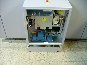
- Autoloader service door (located beneath the cassette feeder motor).
- Loosen the timing belt.
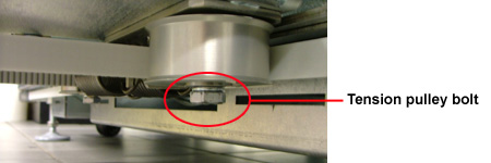
- Use an M17 wrench to release the two tension pulley bolts.
The bolts are located on the underside of the tension pulleys.
- Use an M10 wrench to close the lead tension screw and thus decrease
the tension on the timing belt.
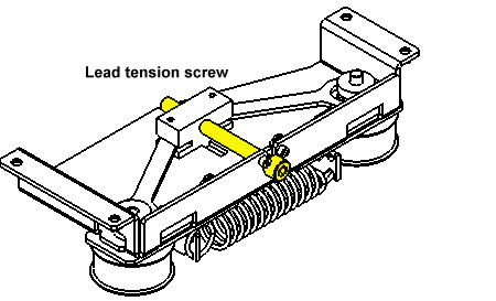
Note: When
the lead tension screw is closed, the tension spring expands, causing
the two tension pulleys to move further apart. As the distance between
the two tension pulleys increases, the timing belt becomes slacker
(less tense). When the tension on the timing belt is slack enough
the belt falls off the four pulleys (located on each corner of the
MCU).
- Use a tape measure to determine the approximate height
from the MCU floor to the ends of the first cassette tray runners.
Note: Each runner end
is located near to one of the four lead screws.
By measuring the height of each runner end to the MCU floor, the service
engineer is able to determine the lowest runner end.
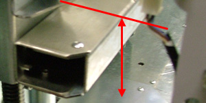
- Manually rotate each individual lead screw pulley until the height
from the MCU floor to each runner end is approximately equal (±2 mm).
- Use the height of the lowest runner end (see step
3) as the reference height for the three remaining runner ends.
- Each full rotation of a pulley adjusts the height of the runner
by approximately 5 mm.
- Install the timing belt.
- Make sure the teeth on the timing belt are facing the teeth on
the pulleys.
- Make sure both sets of teeth mesh.
- Increase the tension on the timing belt by opening the tension
screw until it rotates freely.
Note: As the screw opens, the
tension spring contracts, causing the two tension pulleys to move
closer together. As the distance between the two tension pulleys
decreases, the timing belt becomes more tense.
- Retighten the two tension pulley bolts.
- Carefully move the MCU elevator until cassette
number four is at the user door level.
- Loosen the timing belt (see step 2).
- Insert the lead screw jig (690-01031A) close to the end of a specific
runner.
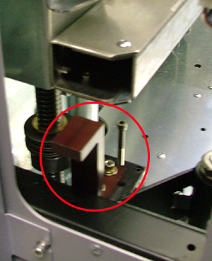
- Place the measuring gauge jig (690-01056A) on the runner surface end
closest to the jig.
- Make sure the tail of the gauge is touching the top of the jig.
- Set the gauge to zero.
Note: The height of
this runner end will be used as the reference height for the three
remaining runner ends.
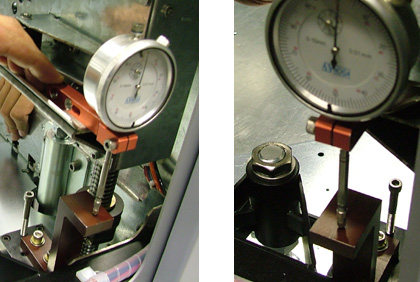
- Use the jig and the gauge to individually measure the height of the
remaining three runner ends. Rotate the individual pulleys so that the
three runner ends are at the same height as the reference runner end.
Important: The allowed
tolerance deviation is 0.5 mm.
- When all four runner ends are at the same height, reinstall the timing
belt (see step 5).
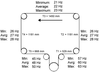
- Use the frequency sensing device and the table
below to check the frequency of vibrations on different sections of
the timing belt.
|
Section Length
|
Frequency min.
|
Frequency max.
|
|
mm
|
Hz
|
Hz
|
|
1181
|
26
|
28
|
|
1450
|
21
|
23
|
|
668
|
45
|
50
|
|
529
|
57
|
63
|
- Remove the jig and gauge.
- Calibrate the MCU.
- Run the MCU sequence script.
- Reinstall the following panels:
- All the skirting panels that cover the timing belt
- Autoloader service door (located beneath the cassette feeder motor)
- MCU rear panel
- MCU E-box panel
- MCU E-box cover
|

