Solution |
|
- Open the rear hood and the front hood and turn the hazard key to the mechanical hazard mode.
- Optional: Engage load table and engine step enable to be able to control the the sequence of loading and to stop to
to inspect each state.
- Queue a plate load [single or dual] - whichever one generates the error.
- Watch the plate approach the LEC. As the plate is loaded and one of the registration steps fails, the device will
automatically retry to do each step 2 more times before generating an error.
Determine the following:
- Question 1 - As the plate enters the LEC, is it parallel to the LEC or rotated either clockwise [CW] or counter clockwise [CCW]?
- Question 2 - As the plate contacts the registration pins [before preload is applied], does it:
- Rotate into contact with the second pin and does not buckle before stopping for the load table preload,
- Rotate and then buckles after contacting the second pin before stopping for the load table preload, or
- Buckle against the first pin before stopping for the load table preload. For example, the plate edge touches the first pin
and then continues straight to the second pin?
- Question 3 - Once the preload is applied and the device experiences the error, does it:
- Buckle between the vacuum cups and the LEC,
- Buckle between the vacuum cups and the LEC equally, or
- Buckle more on the one side than the other side?
When error #40514 occurs, check which sensor is included in the description of the error (0, 1, or 2).
- If the plate buckles between the vacuum cups and the LEC:
- The stepper motor and pulley couplings may be slipping.
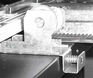
- Check that the load table belt tension is correct. Ensure the fastener in the spring is set to match the flange in the bracket
and that the securing fasteners are tight [look under pullout table support beam].
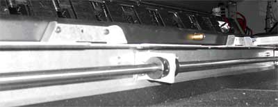
- Check for loose load table drive shaft fasteners - tighten as required.
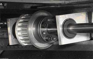
- Check and tighten the couplings after confirming the alignment is correct.
- The vacuum cups may be slipping under the plate.
- Clean the vacuum cups.
- Check the vacuum generator and the vacuum switch.
- If the plate buckles between the vacuum cups and the LEC equally:
- If the plate rotates into contact with the second pin and does not buckle before stopping for the load table preload:
- Reduce the preload value.
- Check the electronic registration system (see Appendix A).
- If the plate does not make good contact with the registration pins:
- Remove the plates and rotate the plates in the cassette bay or on the pullout load table during loading.
- Reduce the preload value.
- If the plate buckles more on the one side than the other side:
- Check if the plates are loaded correctly in the the cassette or on the pullout load table.
- Check the fetcher for loose bearings or fasteners.
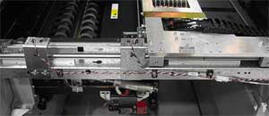
- If question 2 above has the second or third answer:
- Check the load table front beam for protruding screws or rivets.
- Check the load table traveler vacuum cup assemblies for smooth side to side motion when in the neutral position.
- Check the load table pullout frame arms for UHMW tape applied to the inside top corner. The tape will likely show
signs of damage. Remove the tape.
- If the plates are wavy, remove them and rotate the plates 180 degrees in cassette bay or on the pullout load table
during loading.
- If question 2 above has the first answer:
- Reduce the preload value.
- Check the electronic registration system (see Appendix A)
Appendix A - Checking the electronic registration system.
To determine which pin circuit is causing the registration error, load several plates using the Continuous Load
(manual bypass) table and follow the instructions below.
Test option 1
- 6 pin registration system - load a large plate on pins 3 and 4.
- If a single plate centered on 697 mm pins is successful: Load plates on pins 1 and 3 , 4 and 6.
- If it fails on dual plates, look for the plate that is not generating registration (for home plate: check pins 1
and 2; for away plate: check pins 5 and 6).
- If it succeeds on dual plates, the electrical part of the registration system is working.
- If a single plate centered on 697 mm pins fails: Check pins 3 and 4
- 4 pin registration system - load a large plate on pins 3 and 4.
- If a single plate centered on 697 mm pins fails, load a medium plate on pins 1 and 3.
- If a single plate on 504 mm registration fails, load a small plate on pins 2 and 3.
- If a single plate on 280 mm registration fails, check all pins 1, 2, 3, and 4.
- If a single plate on 280 mm registration is successful, check pins 1 and 4.
- If a single plate on 504 mm registration is successful, check pin 1.
- If a single plate on 697 mm registration is successful, load 1 medium plate on pins 1& 3.
- If a single plate on 504 mm registration fails, check pin 2.
- If a single plate on 504 mm registration is successful, load 1 plate on pins 2 &3.
- If a single plate on 280 mm registration fails, check pin 3.
- If a single plate on 280 mm registration is successful, it would appear that the electrical part of the registration
system is working.
Test option 2
- Cut a piece of printing plate large enough to cover three contact on the contact block. Tape the piece of plate alum side up
onto the contact block over pins 1 to 3.
- Initialize the drum.
- If the device error on a detected short across pins 1-2 or 1-3 then you know that the electronic registration system for those
pins is working.
- Repeat for pins 4 to 6.
|

