Home | Contact Us | Submit Troubleshooting Info | Search | Help
Output | Software Solutions | Proofing | Color, Screening and Calibration | Scanning | Digital Photography | Consumables | POS
Home | Contact Us | Submit Troubleshooting Info | Search | Help
Output | Software Solutions | Proofing | Color, Screening and Calibration | Scanning | Digital Photography | Consumables | POS
Drawings/photos | Firmware | Parts | Procedures | Requirements | Reference Documents | Specifications | Troubleshooting
Currently, the edge detection of plates on the drum is done by the thermal head's focus laser. To improve on the accuracy and speed of
edge detection, an edge detect camera can be used. One of the major advantages of the camera system is that it can do edge detection while
the drum is spinning—unlike the focus laser that requires the drum to be stationary. Another important advantage is that the edge detection
can be configured to be done anywhere around the drum.
The main system components for the camera are a camera block, a LED driver board, and the Gigabit Main Control Electronics (GMCE) board
(version D or later). The camera used is a black and white ultra-miniature camera (see specifications below for details).
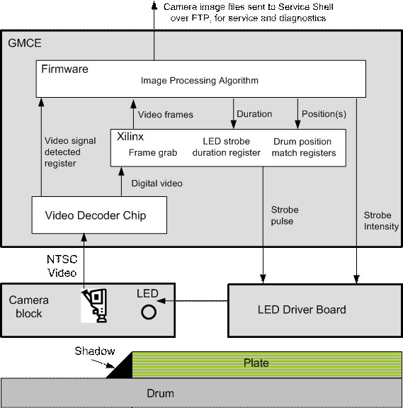
The camera block provides a NTSC video signal to the GMCE board's video decoder. The GMCE board sends the video frames to the system
firmware and also controls the LEDs on the LED driver board.
The edge detect camera can be used on devices that have either a TH2 or a TH3.
This camera replaces the discontinued Weldex model WDH-2500bs.
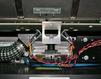
This camera has been discontinued.
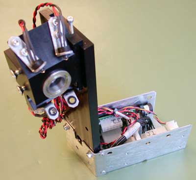
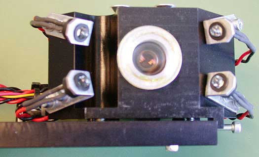
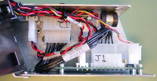
The generation 2 camera assembly can be distinguished from the old camera in the following ways:
Shows the edge detect strip
 |
Shows the drum
 |
Shows a plate (right), shadow, and the drum
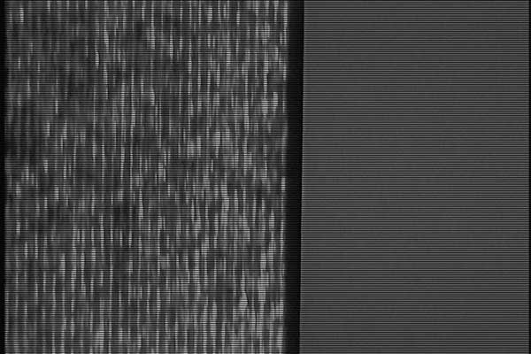 |
Shows plate edge over the edge detect strip
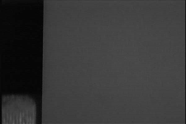 |
Edge detect at a configurable drum position
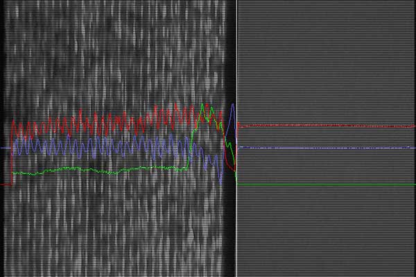 |
See the Procedures page.
camera : shows how many LED boards are connected and looks for a valid video signal (useful for troubleshooting)strobe test : tests the four LED strobe lightsedgecam : displays all of the edge detect camera NVS parametersoption camera-edge-detect : to enable or disable the camera (must reset after changing this parameter)set edgecam strobeduration : LED strobe duration in micro sec (default is 20)set edgecam strobeintensity : LED strobe intensity range 0 to 15 (default is 4)set edgecam msoffset : mainscan camera position in degreesset edgecam calibmediathick : media thickness in microns (used for camera calibration)set edgecam scale : scale in microns per camera pixel (used for camera calibration)set edgecam ssoffset : subscan offset between camera and focus laser in millimetersSee the Troubleshooting page.
 Images created by the strobe test command are saved indefinitely on the workstation. This will enable you to compare images taken six
months back with current images to see if the camera or LEDs are partially obscured by debris. To obtain images for comparison, type:
carriage moveto 100
drum move 100
strobe test