Home | Contact Us | Submit Troubleshooting Info | Search | Help
Output | Software Solutions | Proofing | Color, Screening and Calibration | Scanning | Digital Photography | Consumables | POS
Home | Contact Us | Submit Troubleshooting Info | Search | Help
Output | Software Solutions | Proofing | Color, Screening and Calibration | Scanning | Digital Photography | Consumables | POS
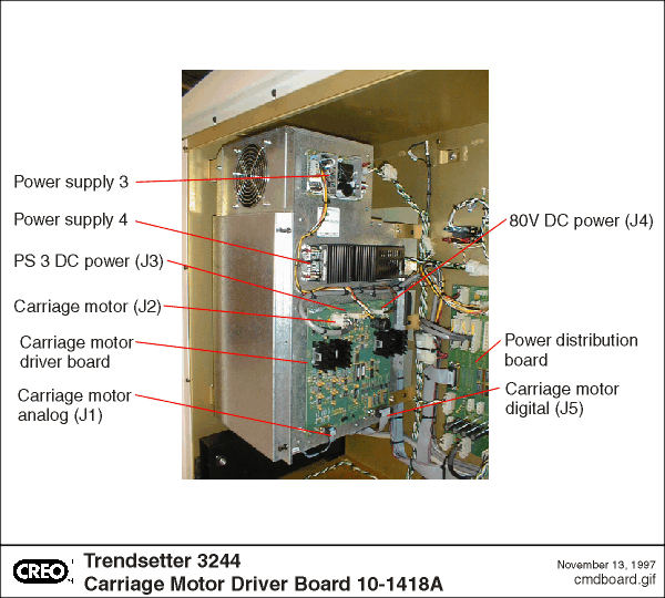
Connectors | Indicators | Test Points | Photograph
See also:
Assembly Drawing
| Connector | Description | Cable Name | Part number |
| J1 | ANALOG IN 9 PIN, PCB, DSUB,SHIELDED CARRIAGE DRIVE (CONNECTED TO BP(J24)) |
CD-A-BP | 10-3324A |
| J2 | CARRIAGE MOTOR 6 PIN,PCB HDR, MATE-N-LOK |
CM-CD | 10-3270A |
| J3 | DC POWER INPUT (5V, 12V, -12V) 6 PIN,PCB HDR,LIN, MATE-N-LOK |
PS3 | 10-3371 |
| J4 | 80 V DC POWER INPUT 2PIN,PCB HDR MATE-N-LOK |
THERMAL DC HARNESS | 10-1437A |
| J5 | CARRIAGE MOTOR DIGITAL I/O CONNECTED TO BP(J29) 25PIN,PCB,DSUB, SHIELDED |
CD-D-BP | 10-3325A |
| Light | Color | Description |
| D6 | GRN | +5V |
| D7 | GRN | +12V |
| D8 | GRN | -12V |
| D13 | RED | CM OVER |
| D21 | GRN | VCM |
| Test Point | Description |
| TP1 | CMA |
| TP2 | GND |
| TP3 | BCUR |
| TP4 | GND |
| TP5 | CMB |
| TP6 | ACUR |
| TP7 | +5V |
| TP8 | +12V |
| TP9 | -12V |
| TP10 | GND |
| TP11 | VCM |
| TP12 | GND |
| TP13 | +5VREF |
| TP14 | LOCL |
| TP15 | -5VREF |
| TP16 | GND |
| TP17 | +2.5VR |