Home | Contact Us | Submit Troubleshooting Info | Search | Help
Output | Software Solutions | Proofing | Color, Screening and Calibration | Scanning | Digital Photography | Consumables | POS
Home | Contact Us | Submit Troubleshooting Info | Search | Help
Output | Software Solutions | Proofing | Color, Screening and Calibration | Scanning | Digital Photography | Consumables | POS
Description | Drawings/Schematics/Photos | Error Messages | Firmware | LEDs | Replacing a Board
The tasks of a GENINE board are to:
There are 4 GENINE boards in the Magnus VLF with MCU, all identical and all using Canbus connectors.
| Board | Description | Location |
| GENINE 0 | Controls the fetcher | Base device power box |
| GENINE 1 | Controls the load table and side ejector | Located on the mainframe above the power entry box |
| GENINE 2 | Controls the unload table | Located under the far, rightside panel of unloadtable |
| GENINE 3 | Controls the MCU, SSR and picker | MCU power box |
A GENINE board is used in the power box of the Trendsetter AL/NEWS option, and in the Spectrum option.
There are 4 GENINE boards in the Trendsetter VLF AL, all identical and all using Canbus connectors.
| Board | Description | Location |
| GENINE 30 | Controls the y-axis | Trendsetter VLF power box |
| GENINE 31 | Controls the MCU or SCU (garage and docking station) | MCU or SCU |
| GENINE 32 | Controls the picker | Picker arm |
| GENINE 34 | Controls the conveyor | Conveyor |
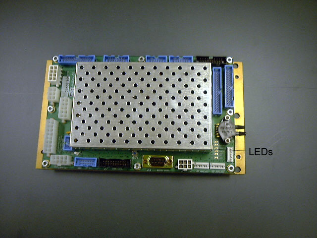
See photo for the location of LEDs on a GENINE board.
- pwr (=power)
Should be lit steadily. If it isn't, replace the board.- cancom (=Canbus communications)
- heart
Should be flashing at a rate of 1 second on, 1 second off. If it flashes incorrectly it is in a constant boot mode. Replace the board.- intr (=interrupt)
Should be lit steadily with a light orange color. If it is glowing red, replace the board.- debug/service
Should not be lit. If it is glowing red, replace the board.- reset
[23204] SCON: Failed to establish SCON communications
[22202] ALE2: GENINE %d satellite board %s cable disconnected
[22351] ALE2: GENINE4 satellite board %s cable disconnected
When replacing a GENINE board, bolt it on tightly. The contact area cools the
stepper motor driver.
Checking GENINE board installation