Home | Contact Us | Submit Troubleshooting Info | Search | Help


    Output | Software Solutions | Proofing | Color, Screening and Calibration | Scanning | Digital Photography | Consumables | POS


Replacing the Picker 3 guide cables


Product

 
  • Trendsetter® Autoloader
  • Trendsetter NEWS

Requirements

  • Two replacement Picker 3 guide cables: 50-1765
  • FCO E042 (if not already installed)
     Kit # 05-0196: New shoulder bolt for Picker 3 guide cables (Autloaders with serial numbers SA461 and later have the new shoulder bolts)


WARNING: This procedure requires you to turn off the compressed air supply to the output device. You must ensure that the compressed air does not come back on and re-energize the picker assembly while you are working on it, because this results in sudden, unexpected movement of the picker assembly, which can seriously injure any body part in its path.


Procedure

After removing the old Picker 3 guide cables, install the new cables (50 1765A) as described below.
 
  1. Turn off air to the output device. This allows you to raise the picker to a more accessible position.
     
    Note: On Trendsetter Autoloader devices, take care not to damage the Mylar strip protecting the vacuum cups. (NEWS devices do not use the Mylar strip.)
     
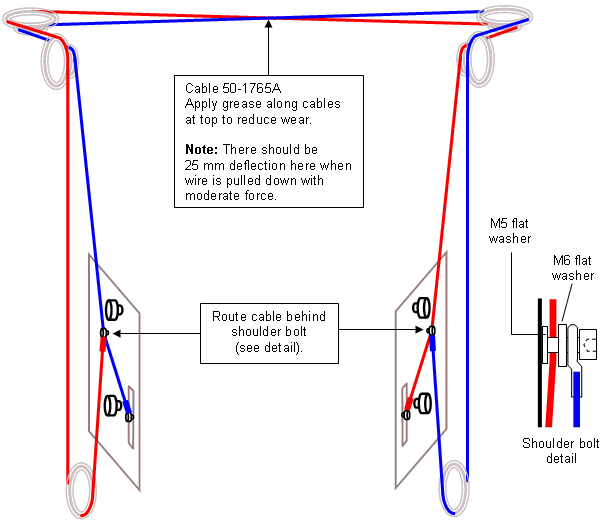
  2. Attach the steel guide cables (50-1765A) to the shoulder bolts on each side of the picker head (see diagram, below).
  3. Route the steel guide cables around the lower and upper pulleys as shown in the diagram.
     
    Note: Use masking tape to hold the cables in position until you are ready to apply tension. 
     
  4. Apply grease to the cables at the top of the picker assembly to reduce wear.
  1. Route the other end of each cable around the shoulder bolts in the picker head (see drawing above), and attach it to the M5 nylock nut in the slot near the front of the picker head.
  2. Adjust the cable tension at this point so that the cables do not fall off the pulleys.
  3. Center the picker within 2 mm and allow 1 mm of side-to-side play.
  4. Make sure that the picker head is in the retracted position. The head should not be reaching for the load table.
  5. Loosen the bottom screw of one rail.
  6. Move the picker down by actuating the solenoid.
  7. Center the picker within 2 mm and allow 1 mm of side-to-side play in the bottom position.
  8. Move the picker up and recheck the side-to-side play.
  9. When the picker guide cable is correctly adjusted, close the load bay access door and then turn the air supply to the output device back on.

See also

  Picker 3 upgrade procedure:

Technical contact(s)
 

Content owner: Doug Jeffery
See the Escalation page for escalation contacts:

Date submitted
 

09 Dec 2004


    Copyright © 2005 Creo Inc. All rights reserved. Confidential. Back to top.