

Home | Contact Us | Submit Troubleshooting Info | Search | Help
Output | Software Solutions | Proofing | Color, Screening and Calibration | Scanning | Digital Photography | Consumables | POS
Home | Contact Us | Submit Troubleshooting Info | Search | Help
Output | Software Solutions | Proofing | Color, Screening and Calibration | Scanning | Digital Photography | Consumables | POS
|
|
||
Product |
|
|
|
|
||
|
|
WARNING: Failure to follow Kodak’s safety policies and procedures for
field engineers may create a dangerous situation that could result in
serious injury as well as damage to the output device. For more information, see the Safety page. |
|
|
|
||
Procedure |
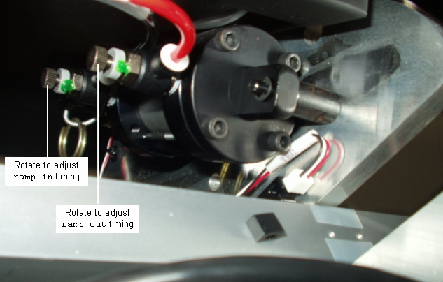
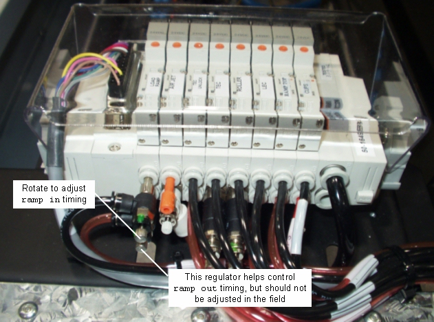
There are four regulators that control the
timing of the ramp in/out actuators. Two of them are on the away side ramp
in/out cylinder, and two of them are on the home side manifold.
|
|
|
||
|
||
|
Setting the ramp in/out actuator timing is an iterative process, because when you adjust one regulator, it changes the air flow through all the others, requiring them to be adjusted, too. The goal is not only to achieve the correct ramp in/ramp out timing, but also to have both ramp in/out cylinders move in and out evenly. Important: The ramp out regulator (the bottom one on the side of the home side manifold) should not be adjusted in the field. Doing so will require a lot of time consuming adjustments to the other three regulators in order to get the ramp in/out actuators functioning properly. |
||
|
|
||
Test |
After making adjustments to regulators
controlling the speed of the ramp in/out actuators, enter the engine
time command and compare the times reported with the table in the
Measuring engine, picker, and table actuator times and
adjusting actuators document.If necessary, readjust the regulators and try again. |
|
|
|
||
Technical contact(s) |
Content owner: Frank van
Eerdt
|
|
Date submitted |
09 Jun 2004 |
|
