Home | Contact Us | Submit Troubleshooting Info | Search | Help


    Output | Software Solutions | Proofing | Color, Screening and Calibration | Scanning | Digital Photography | Consumables | POS


Adjusting the table rotate on/off actuator regulators


Product

 
  • Trendsetter® NEWS™
  • Trendsetter Autoloader
  • ContinuousLoad for Trendsetter

  WARNING: Failure to follow Kodak’s safety policies and procedures for field engineers may create a dangerous situation that could result in serious injury as well as damage to the output device.
For more information, see the Safety page.

Procedure


To access the rotate on/off actuator:

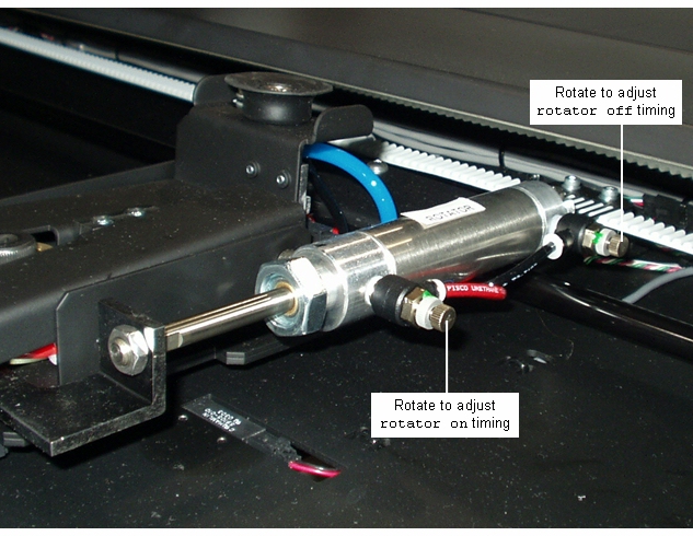
On devices with the rotator option, the rotate on/off actuator is located on the away side of the rotator assembly.

  1. In Service Shell’s Device Monitor command box, enter command:
    table up
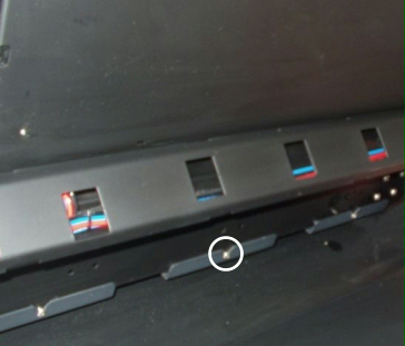
  2. With a 3 mm hex key, loosen, but do not remove, the middle screw attaching the center panel of the unload table to the bottom of the unload table frame.

  3. Enter command:
    table down
  4. Use a 3 mm hex key to loosen the middle screw fastening the center panel to the exit side of the unload table.
  5. Move the traveler to the rotate position:
    table move rotate
  6. Gently lift up the end of the center panel closest to you, and then push it away from you (toward the entry side of the unload table), so that the slot in the other end is no longer in contact with the screw you loosened in step 2.
  7. Slide the center panel to your right, out of the way of the traveler and vacuum cups. The rotate actuator is attached to the away side of the traveler/rotator assembly.

To adjust the regulators on the rotate on/off actuator:

To put back the unload table center panel and check for levelness:

  1. Reposition the unload table center panel you moved in step 6 of To access the rotate on/off actuator, above.
  2. Reach around to the entry side of the unload table and feel the slotted mounting plates underneath to ensure that the slot is aligned with, and wrapped around the center screw you loosened in step 2.
  3. Use a 3 mm hex key to tighten the screw you loosened on the exit side of the unload table in step 4.
  4. In Service Shell, enter command:
    table up
  5. Tighten the center screw underneath the unload table that you loosened in step 2.
  6. Enter command:
    table down
  7. Check the positioning of the panels:
    1. Place a long straight edge on top of the panels on the unload table to verify that they are properly aligned to the same height.
    2. Enter command:
      table cups up
    3. Check to ensure that the vacuum cups are above the height of the unload table.
    4. If necessary, adjust the positioning of the panels by repeating the relevant steps above.

Test

  Enter the table time command and compare the times reported with the table in the Measuring engine, picker, and table actuator times and adjusting actuators document.

Technical contact(s)
 

Content owner: Frank van Eerdt
See the Escalation page for escalation contacts:

Date submitted
 

04 Jun 2004


    Copyright © 2005 Creo Inc. All rights reserved. Confidential. Back to top.