Solution |
|
- On the motor end of the drum (bal1), rotate the drum pulley so that you have a new engage position for the pulley/detent mechanism. Here's how:
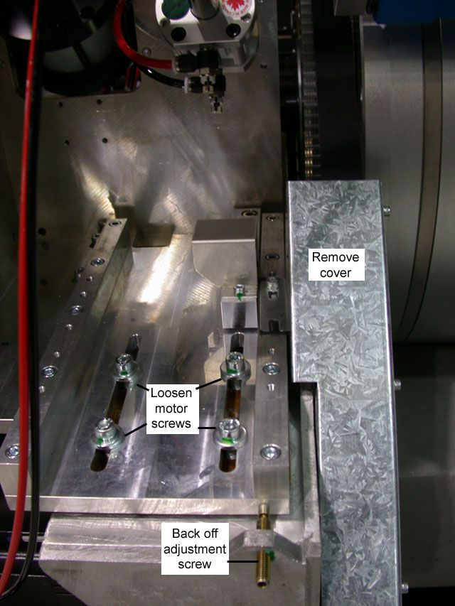
- Release belt tension by loosening the motor. photo
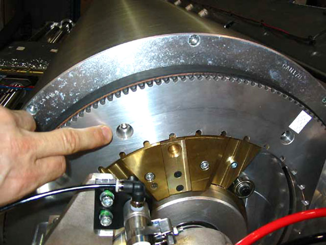
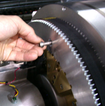
- Remove the six M8 screws from the drum pulley.photo 1 | photo 2
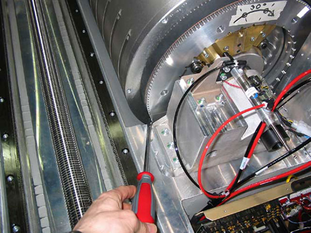
- Rotate the drum pulley by one hole (30 degrees). It should rotate easily by hand. If it doesn't, use a screwdriver as a lever against the teeth of the pulley. photo
- Reattach the M8 screws and adjust the belt tension (Procedure: Adjusting the drum drive motor belt)
- Replace the detent mechanism (see FCO E269)
- Align the balance actuator (Procedure: Adjusting the balance actuation assemblies)
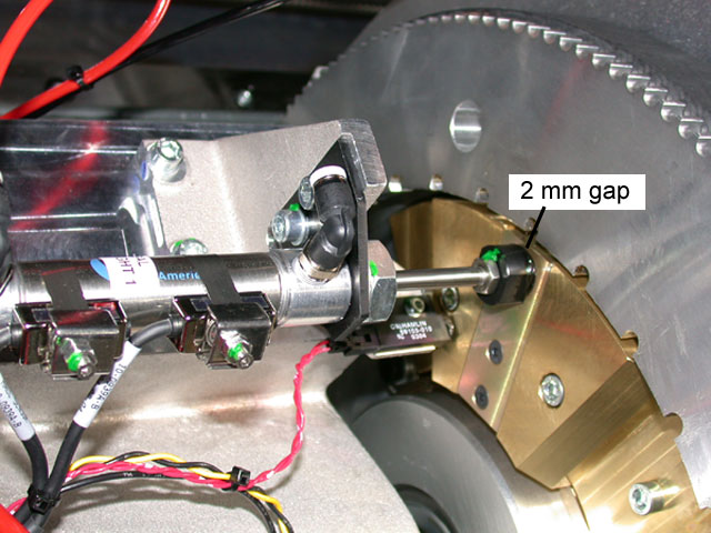
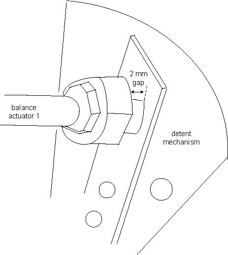
Note: Adjust the actuator so that there is a 2 mm gap between it and the detent mechanism. photo | drawing
How to adjust the actuator:
- Unscrew the lock nut and adjust the length of the locking tip mechanism.
- Use the black airline on the actuator to apply air to the fitting and engage the mechanism.
- Check that gap is 2 mm. This 2 mm gap will ensure that the locking pin does not overstress the detent mechanism, and that the drum pulley will lock and unlock properly.
For details, see Adjusting the balance actuation assemblies
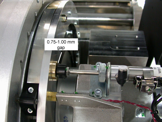
- Go to the encoder end of the drum (bal2) and check that the balance actuator is aligned properly there. There should be a 0.75-1.00 mm gap between it and the brass engagement ring on the detent mechanism. photo
The alignment will probably be fine, but if an adjustment is needed, here's what to do:
- Unscrew the lock nut and adjust the length of the locking tip mechanism.
- Use the black airline on the actuator to apply air to the fitting and engage the mechanism.
- Check that gap is 0.75-1.00 mm.
For details, see Adjusting the balance actuation assemblies
- Check the set al bdo position and calibrate if needed. See the last 2 pages of the Adjusting the balance actuation assemblies) procedure.
|