Home | Contact Us | Submit Troubleshooting Info | Search | Help
Output | Software Solutions | Proofing | Color, Screening and Calibration | Scanning | Digital Photography | Consumables | POS
Home | Contact Us | Submit Troubleshooting Info | Search | Help
Output | Software Solutions | Proofing | Color, Screening and Calibration | Scanning | Digital Photography | Consumables | POS
A Field Change Order (FCO) contains only the information from an Engineering Change Order (ECO) that relates to service.
To look up a customer's install base, go to the Customer Library and search by customer name. Click the Installed Base tab.
ASAP | FYI | Next visit | Next failure | Next PM
| FCO | Date Posted | Description | Service Actions | Priority |
|---|---|---|---|---|
| D788 | Sep 2000 | The rubber boot insulator, part #18-3243, is a safety hazard and must be replaced with part #18-3355. | D788 upgrade procedure
BOM | ASAP |
| C216 | Jun 1998 | Keyswitch SIO field retrofit. | Retrofit required on all Trendsetter VLFs
in the field.
See the retrofit procedure document. |
ASAP |
| B573 | May 1997 | Releases new laser plate fly-off sensor | Upgrade required on VB1, V05, V18, V22, V25, V26 and BB1-BB9. | ASAP |
| B510 | May 1997 | Engine backbone centering upgrade, TEC clamp lock cylinder mounting upgrade | Upgrade required on VB1, V05, V18, V22, V25, V26 and BB1-BB9. | ASAP |
| FCO | Date Posted | Description | Service Actions | Priority |
|---|---|---|---|---|
| CA06905 | 20 Jun 2005 | Heat exchanger jumper plug added | A jumper plug has been added to the heat exchanger.
Kit: 512-00298A Procedure: See the note on the Heat Exchanger page. Installation and Maintenance: Heat Exchanger for Trendsetter VLF |
Next visit |
| E797 | May 2002 | Extra counterweights for table balancing - field rework
Related FCOs - E345 and E679 |
Four extra counterweight brackets (57-7289A) are added to the main counterweight to eliminate problems with the 5080 and 5880 table being unbalanced when running large plates.
Note: This applies to the base machine only. The upgrade kit 05-2041 has been updated with the extra counterweights, and the field upgrade instructions 73-0215A are also revised. |
Next visit |
| E712 | Apr 2002 | New Kit for UDRC-B Debris Removal System (F-speed) Upgrade
Related FCO - E399(R1) |
Upgrade kit 05-2042 replaces 05-0239. A blanking plate has been added for the water cooling connection.
Note: 05-2042 has since been replaced by 02-4468 (FCO CA00232, Feb 2003) Order form |
Next visit |
| E497 | Feb 2002 | LEC Pushbar Upgrade | Implement on B639 and before.
Kit: 05-2036 Procedure: LEC Pushbar Installation Procedure |
Next visit |
| E399(R1) | Jan 2002 | Field Upgrade to UDRC-B Debris Removal System (F-speed only, at request of DU) | For field upgrade instructions, see 72-3619A.
Upgrade kit 05-2042 Note: 05-2042 has since been replaced by 02-4468 (FCO CA00232, Feb 2003)). Order form Complete the Site Questionnaire for DR Upgrade, 72-3656B before ordering the upgrade kit. |
Next visit |
| E345 | Aug 2001 | Head Guards Upgrade
Related FCOs - E679 and E797 |
For 5080/5880 tables, use upgrade kit 05-2041.
For field upgrade instructions, see 73-0215A. |
Next visit |
| E150 | Apr 2001 | LEC Hinge Rod Repair | For instructions on how to repair the hinges in the field, see LEC Hinge Repair Procedure | Next visit |
| tbd | Apr 2001 | Improving Desiccant Box Reliability | For instructions on how to improve the reliability, see Improving Reliability for the Desiccant Box . Applicable to machines with V-heads only. | Next visit |
| E040 | Feb 2001 | Service Key Removal | Remove the service key from all output devices. | Next visit |
| D973 | Feb 2001 | Patent Label Placement | #74-3305A, Patent label to be applied to all output devices and thermal heads. | Next visit |
| D501 | May 2000 | Releases UDRC-B upgrade kit for 40W V head | Kit 02-4468A (released under CA00232 to replace 05-0156 and 05-2042)
VLF Platesetter/Trendsetter VLF UDRC-B Installation/Upgrade Procedure, 40W, V-head order form |
Next visit |
| C961 | Jul 1999 | Vacuum Plugs on drums cause
reflections.
Encoder is unreliable. |
Install decals 74-3236A on all drums with
vacuum seal discs behind the encoder disc.
Replace encoder assemblies 32-3011B or 32-4047A with 32-4047B if encoder still failing after cleaning and aligning. |
Next visit |
| C904 | Jun 1999 | Customers can't always find the machine serial number when placing a call to the response center. | Attach a label with a Service Reference Number to each machine in the field. | Next visit |
| B342 | Feb 1997 | Incorrect wording on Laser Hazard sticker - new sticker required | Upgrade required on BB1-BB9. | Next visit |
| B269 | Jan 1997 | Changing PS3 from linear to switching power supply to comply with CSA and CE certification | Update the 10-1440A power supply next
service call.
Upgrade required on BB1-BB9. |
Next visit |
| FCO | Date Posted | Description | Service Actions | Priority | |||||||||
|---|---|---|---|---|---|---|---|---|---|---|---|---|---|
| CA10961 | 08 May 2007 | Omron switch kit replaced.
The existing replacement kit is inadequate for 22 awg wire. |
Replace 15-3263 omron switches with kit 518-02230A on next failure.
Procedure: Omron Switch Replacement Procedure. |
Next failure | |||||||||
| CA05308 | 09 May 2005 | Controlled Release 3.0 available. | For details on this controlled release, see the Control/settings page. | Next failure | |||||||||
| CA05236 | 28 Feb 2005 | Implementation of heat exchanger for the VLF product line. | Replace defective chillers with heat exchangers. See the Heat Exchanger page for details. | Next failure | |||||||||
| E897 | Oct 2002 | Plate sensors on load ramp, load table, and unload table lose connection due to fretting on the contacts between the cable and sensor. Replacement high flex cables have more reliable connectors. Sensors must be replaced in case of corrosion caused by previous connectors. | Kit #512-00006. See Replacing Sensors and Cables - FCO E897 for procedure. | Next failure | |||||||||
| E788 | Sep 2002 | Table extension stiffeners to correct sagging table wings. | Affects all Trendsetter VLF machines prior to B692. BOM
For instructions on installing the stiffeners, see 77-0247A. |
Next failure | |||||||||
| E921 | Jul 2002 | Longer cable/hose for UDRC-B | The cable and hose are lengthened from 3m to 7.6m so that the unit can be moved farther away to reduce noise. The Ablative Media Upgrade kit 02-4326A is updated BOM with the new attachment kits 11-1068B and 11-1069B. | Next failure | |||||||||
| E710 | May 2002 | New frame holes for 5880 table up switch bracket
Related FCO: E612 |
To prevent bending of the table up switch bracket (57-6492B) on 5880 machines, it must be installed 30mm to the right of the bracket position for 5080 machines. This involves drilling two new holes in the table support frame (57-1474D). See Drilling Holes for the 5880 Table Up Bracket. | Next failure | |||||||||
| E612 | Feb 2002 | Table up switch bracket modified
Related FCO: E710 |
The table up switch bracket is susceptible to bending, so a new bracket design has been implemented. Part #57-6492B replaces 57-6492A.
Also released on this ECO: Upgrade kit 05-2043 replaces 05-0077 (ECO C664) |
Next failure | |||||||||
| E679 | Mar 2002 | Extra counterweights to balance 5080 tables
Related FCOs - E345 and E797 |
Re-install head guards using upgrade kit 05-2041, which contains extra counterweight brackets.
For field upgrade instructions, see 73-0215A. |
Next failure | |||||||||
| E453 | Oct 2001 | Dehumidifier (DHU) upgrade
Supersedes FCO E346 Related FCO - E246 |
Upgrade at next failure of the Dessicant box. See FCO E453 for kit number and installation procedure. | Next failure | |||||||||
| D739 | Oct 2001 | Replace Debris Removal Morgan Cabinet with Universal Debris Removal Cabinet (UDRC). | Replace Morgan Cabinet with UDRC on next cabinet failure. | Next failure | |||||||||
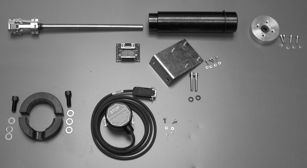
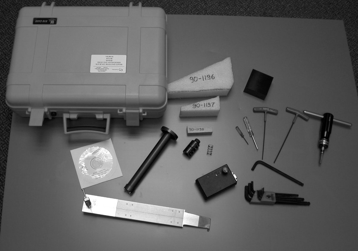
| D992 | Jul 2001 | Shaft encoder upgrade
See CA08342 for updated parts and tool kits Upgrade kit: 05-0195 BOM | photo Tool: 90-1191 photo | list of owners Test files:
|
Upgrade at next failure of the glass
encoder. See Optical Encoder Failures before doing the upgrade.
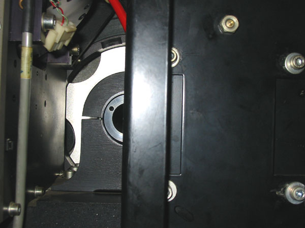
Procedure: Warning: Machines with serial numbers BB01 to B019 cannot be upgraded. A post on the frame blocks access to the encoder, and the drum pin cannot be removed. photo | close-up |
Next failure | |||||||||
| C433 | Aug 1998 | Table Airjet upgrade. Replaces the current throttle valve with a larger diameter version to increase the air flow rate to the table air jets. | Install Table Airjet Upgrade Kit on any VLF
Trendsetter which exhibits inconsistent plate drop during the
loading sequence.
See the table airjet replacement procedure |
Next failure | |||||||||
| C161 | May 1998 | Large ‘slugs’ of oil in the air lines can get past the filters and damage the device. | Install optional Oil Trap system 10-3765A.
Instructions |
Next failure | |||||||||
| C144 | Feb 1998 | The thermal DPE board and the PHI board are replaced by the new FDPE (Fast Data Path Electronics) board | To replace the DPE board:
Order a FDPE kit (part number 10-3762A - includes the FDPE board
(10-3672A) and a memory module (12-4168)).
|
Next failure | |||||||||
| B830 | Aug 1997 | New part numbers for the MPE and ALE boards | You can replace an old board with a new one
as long as the firmware version is 1.02 or higher.
|
Next failure | |||||||||
| B644 | Jun 1997 | Overtightening the thumb screw on the
external SCSI cable can cause the jack screw to become loose.
It may undo when you try to remove the SCSI cable.
A nutplate, 57-4711a, is used to replace the 4-40 nut and lockwasher on the SCSI cable mounting bracket. |
Detail D on Page 4 of BOM
(Platesetter 3244 drawing) shows how the nutplate mounts.
ECO A356 must already be installed, or be done at the same time. Use the Jack screw and nutplate install procedure for SCSI cableJack screw and nutplate install procedure for SCSI cable. |
Next failure | |||||||||
| B522 | Nov 1997 | Carriage motor shaft slips inside of the drive pulley | Upgrade required on machines with serial numbers prior to B62. | Next failure | |||||||||
| B142 | Dec 1996 | LEC upgrade | Next failure | ||||||||||
| A356 | Apr 96 | SCSI cable and jack screw change. Fit new SCSI cable and receiving screws. | Install ECO B644 at the same time. Use the Jack screw and nutplate install procedure for SCSI cable. | Next failure | |||||||||
| FCO C006 | Dec 1997 | Current roller leaves marks on plates.
This ECO releases new EPDM drum rollers. |
Upgrade TSV01 through TSV70. | Next failure |
| FCO | Date Posted | Description | Service Actions | Priority |
|---|---|---|---|---|
| CA01804 | Sep 2003 | Remove MOVs and spark gaps between line and ground
The MOV and spark gaps used to be installed in our machines for added protection against immunity testing and effects of disturbances such as lightning, etc. The MOVs were connected line to line (L-L) and line to ground (L-G), with series connected spark gaps. However the line to ground connections are no longer permitted by the safety standards unless the MOVs meet basic insulation requirements (1500 V AC), which defeats most of the purpose of providing them. Also the machines pass the Immunity tests without the MOVs. Also MOVs break down over time, depending upon the number and severity of over-voltage disturbances they have been subjected to, so there is a recommendation that they be replaced periodically (which Creo has never done). When L-L or L-G MOVs break down, they can continue to conduct current after a disturbance (the spark gap can help to reduce this occurrence which is important for L-G MOVs as the leakage current will start to increase). Eventually the MOVs will conduct up to and including short circuit, at which time the MOVs will heat up and rupture and/or burn. The end result can be either the main CB (or branch circuit breaker) tripping due to s/c condition (and keep tripping upon reset) or the MOVs can open circuit with or without visual damage. New machines are no longer designed with MOVs and spark gaps. For older machines still being manufactured and/or refurbished, we should delete the MOVs and spark gaps from the BOM and remove the components from the machine. For existing units in the field, we should advise service of failure modes of MOVs, and be proactive by removing the components from units on future service calls when time permits. |
Creo MPE devices are no longer being shipped with metal oxide varistors (MOVs) and spark gaps between line and ground. The MOV assembly (part number 10-3616B) should be removed from units in the field at the next PM visit, by unplugging 10-3616B from J13 on the PDB board. Serial numbers B892 and later (and also B887) already have the MOV assembly removed. |
Next PM |
| E269 | July 2001 | Pulley end drum balancer reliability
problems.
Upgrade kit - 05-0233 |
Upgrade drawing and instructions - Upgrade drawing 05-0233 | Next PM |
| E286 | July 2001 | Install check valves to prevent backbone
from dropping onto engine if air supply fails.
Upgrade kit - 05-0232 |
Upgrade all machines up to and including
BA064.
Check Valve Upgrade Instructions - 72-3605A |
Next PM |
| C664 | Dec 1998 | Wedge upgrade, which can be ordered as a kit. | Table wedge upgrade procedure, 73-3258A
Upgrade kit - 05-2043 (replaces 05-0077) |
Next PM |
| FCO | Date Posted | Description | Service Actions | Priority |
|---|---|---|---|---|
| CA11321 | 13 Dec 2006 | F-speed upgrade kit updated | S to F-speed upgrades for devices B1097 and below now require a water cooling upgrade. Devices B1098 and above were all
shipped with water cooled heads.
When doing a S to F speed upgrade, document 725-00021A must be completed and returned Order Management. |
FYI |
| CA08344 | 22 Nov 2005 | Filter/regulator assembly obsolete | The Festo filter/regulators have been replaced with assemblies from SMC. See the Filter/Regulator page for details. | FYI |
| CA08342 | 19 Oct 2005 | Encoder upgrade kit has been updated for new encoders | Tool kit: 90-1191B
Parts kit: 05-0195B Procedure: Upgrading from an Optical Encoder to a Shaft Encoder See also CA05931 and D992 |
FYI |
| CA05961 | 19 Nov 2004 | The 2MB MPE boards (503-00075A) are interchangable with the regular 1MB MPE boards (10-3692B). | There are no firmware changes or changes to the firmware loading procedures between these boards. The 2MB boards are installed in new devices from B1036 onwards, but can be replaced with 1MB MPE boards in the field. No versions of the Trendsetter VLF firmware requires a 2MB MPE board. | FYI |
| CA02367 | Feb 2004 | Extended image option
Note: Customers will be charged for this upgrade, and it is not supported by the Trendsetter VLF Autoloader (except in manual mode) |
A customer requires the ability to load 81.5" plates, which are larger than the current spec and capability. An upgrade kit has been released to install guides that allow proper loading of the larger plate.
|
FYI |
| CA00527 | Feb 2003 | P33 non-Quantum thermal heads for entry level devices | Entry-level devices (Trendsetter 4557, 5064, 5080, 5467 and 5880) are now shipping with the P33 non-Quantum thermal imaging head. The base model has the head set at S-speed and is shipped with a chiller. Upgrades to F and V speeds are available as factory installs or field upgrades, and upgrades to Quantum are also available. The upgrade kits and documents will be released under ECO CA00532.
Restrictions of the base entry level model:
|
FYI |
| CA00532 | Feb 2003 | Release of Ultrafast speed v2.8 thermal 1.x head to VLFs, to allow imaging speeds up to 688 mm/min. | The V2.8 speed option is available as a factory or field upgrade, in both Quantum and non-Quantum versions. They image at 2.8 times the speed of the F head. All V speed Trendsetter VLF devices shipped after Feb 1, 2003 (B766 and later) will use V2.8 head hardware, but only CAM customers using KPG ThermalGold media will have their machine integrated for use at V2.8 speed. | FYI |
| CA00232 | Feb 2003 | VLF devices have been added to the configurable BOM for UDRC-BP, 02-4468A, originally designed only for TS 400/800/NEWS and Lotem 400/800. Upgrade kits 05-0156 and 05-2042 are now inactive. | Fill out the UDRC-BP order form and e-mail it to Order Management to get the correct parts kit. | FYI |
| E424 | Nov 2001 | Emergency stop button lowered. Affects machines B491 and later. | To be replaced on customer request only. Remove existing upper panel and replace with new Upper Panel Assembly 50-2461A | FYI |
| D952 | Dec 2001 | Flextrack tubing change.
EMI shielding on powerbox cables. |
For Cabling changes, see Powerbox EMI Upgrade procedure and use Upgrade kit 05-0217 | FYI |
| D256 | Nov 2000 | A replacement kit has been released for replacement of the electronic registration pin. | The kit should be kept in stock in each
region in case the electrode (#13-4882) fails.
BOM |
FYI |
| D021 | Oct 1999 | Several mechanical safety modifications are
being made. details
Of interest to service: Safety switches are being added for table up/down positions. A relay is being added to cut power to all backbone solenoids when a panel is removed. |
None (for information only).
Starting with serial number B280, the keyswitch will enable/disable the LEC, TEC and roller as well as the carriage and drum, and you will no longer be able to raise or lower the table from the diagnostic monitor. |
FYI |
| C986 | Jul 1999 | Changes are being made so that the EMI
filter can be mounted securely during relocation. details
There will be 2 studs on the AC inlet cover instead of 4, and fasteners are being added to the base-frame rail. |
None (for information only).
The EMI filter will be mounted from the top with a pair of self-tapping screws. See also EMI filter relocation procedure |
FYI |
| C942 | Jun 1999 | Release of Encoder Cleaning Kits:
Encoder cleaning tools kit Encoder cleaning kit (04-0014A) |
See Optical encoder cleaning procedure | FYI |
| C826 | May 1999 | Recent testing on Trendsetter VLFs showed that the 40W exposure head benefits from enhancements to the electrical system which improve RF immunity (and EMI emissions). | Required on all existing V-Head (40W)
machines equipped or upgraded prior to B200.
Machines B159, B186, B191, B192, B197 and B199 have already been done. RF Immunity Enhancements for the 40W V-head Kit,Upgrade,ECO C826,RFI Enhancement EMI Filter Relocation Kit. Trendsetter VLF EMI Filter Relocation |
FYI |
| C637 | April 1999 | Releases the new components and changes necessary to implement electronic registration on TSV machines. | Production machine implementation will begin with B200. Machines from B12 to B199 can be retrofitted with electronic registration. Machines below B12 that have registration blocks secured with potting compound instead of removable screws cannot be retrofitted.
Trendsetter VLF Electronic Registration Upgrade Kit 05-0097 BOM |
FYI |
| C554 | Oct 1998 | Documentation to explain the Neslab CFT33D Chiller Installation and Operation. | All output devices (except the Trendsetter 3230) that utilize the 1.7X Thermal Head will require this externally located Chiller unit to provide cooling fluid to the Head. | FYI |