Home | Contact Us | Submit Troubleshooting Info | Search | Help
Output | Software Solutions | Proofing | Color, Screening and Calibration | Scanning | Digital Photography | Consumables | POS
Home | Contact Us | Submit Troubleshooting Info | Search | Help
Output | Software Solutions | Proofing | Color, Screening and Calibration | Scanning | Digital Photography | Consumables | POS
 Determine the system centerline.
Position the centerline laser plane (#90-1120) outside the work area.
- Set the tripod at 1.5m elevation above the floor.
- Assemble the laser plane for vertical plane operation.
- Mount the laser plane to the tripod.
- Level the laser plane using the bubble level.
- Turn the laser on.
WARNING! Do not look directly into the laser beam.
- Adjust the position of the tripod and the rotation of the laser plane until the reference marks on the floor are met ±1mm. The laser plane will now be displaying the plane that marks the autoloader system centerline.
- Point the laser to the floor under the tripod and mark the position for reference.
Prepare the Trendsetter VLF for the Autoloader upgrade.
- Open the P-Door
- Raise the table
- Switch off the power to the Trendsetter VLF and to the workstation
- Disconnect the AC power cable for the Trendsetter VLF
- Disconnect the workstation cables at the Trendsetter VLF
- Disconnect the airline at the Trendsetter VLF
- Remove all side panels from the Trendsetter VLF
- Remove the Guardrail
Position the 4 lifting jacks (#92-0084).
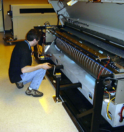
- Place the lifting bars (#56-3266) through the square holes in the engine casting.
- Check that the hose tray is up out of the way of the lifting bars.
- Slide the lifting jacks into the tube ends. Make sure the jacks go in all the way.
Raise the Trendsetter VLF and install the castors.
- Carefully raise the jacks until the bars are bearing against the top of the engine casting holes at all 4 points.
- Place a wood block (#59-3808) under each corner of the VLF Trendsetter for safety.
- Raise the jacks, alternating between the 4 jacks so that the machine is kept level.
WARNING! Do not let any of the lifting points get significantly higher or lower than the others, as this could twist the frame or cause instability.
- Stop lifting when there is enough room to install the castors.
- Check that the wood blocks are still positioned correctly under the corners of the machine.
- Install the 4 screws holding each castor to the Trendsetter VLF frame.
Using jacks to raise and lower the Trendsetter VLF
Lower the Trendsetter VLF onto the castors and remove the jacks.
- Lower the jacks until the lifting bars are no longer touching the engine casting.
- Remove the jacks.
Move the Trendsetter VLF to its new location.
Set the initial height of the Trendsetter using the three adjustable
feet.
- Lay on the floor, reach under the Trendsetter VLF and rotate each adjustable foot down two turns from the fully up position. Use the adjustable foot wrench if required.
Position the Trendsetter VLF in its approximate location according to
the floor layout (±12mm).
For SCU installations, attach the table fixture (#92-0369) to the table
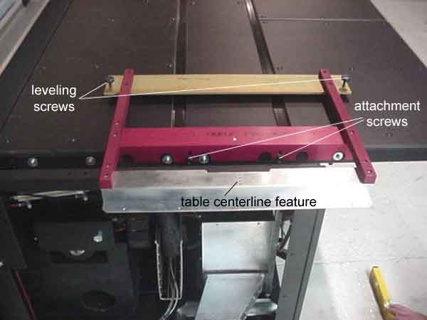
edge on the cassette side, then level the fixture. Proceed to step a.See the drawing: Superjig table fixture
Table fixture (attached to pick side of table)
- Check that the table is down.
- Place the table fixture on top of the table.
- Set the height of the fixture's pivot.
For a Table Left Side pick, rotate the pivot fully clockwise.
For a Table Right Side pick, rotate the pivot fully counter-clockwise.- Place the retainer below the table (the retainer is only required on early production tables that do not have permanent nuts installed).
- Loosely fasten the screws through the table edge. You may want to open the p-door and raise the table to make this task easier.
To adjust the table fixture level:
- lower the table
- calibrate the digital level
- turn it on and let the display settle
- Press the Calibration button. 'cal1' will appear on the display.
- Wait a few seconds till the display has settled again.
- Turn the level around 180° and press the Calibration button again. 'cal2' will appear on the display.
- Wait a few seconds till the display has settled again.
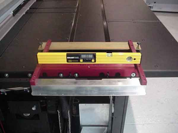
- place the calibrated digital level on the side bar of the fixture, then across the front and rear bars simultaneously
- rotate the leveling screws to adjust the level in both axes to 0° ±0.1°.
Leveling the table fixture
- Tighten the retaining screws.
Align the Trendsetter VLF to the system centerline laser.
- Turn on the laser plane. Recheck that the laser is still in position, and is level.
- Check the centerline reference marks on the table fixture.
- Roll the machine until the laser touches both edges of the centerline marks (one on the table edge and one on the table fixture).
- Turn off the laser plane.
Position the floor plate (SCU installations only).Note: If the floor plate has been shipped in pieces, re-assemble it by following the instructions in Assembling the Floor Plate.
- Slide the floor plate under the Trendsetter VLF.
- Attach the floor plate alignment fixture (#92-0371) to the table fixture.
See the drawing: Superjig floor fixture- Suspend the plumb-bobs (#90-1125) from the floor plate fixture so they hang just above the floor plate.
- Align the holes in the floor plate under each of the plumb-bob tips. Use a mallet, if needed, to bump the floor plate into position. Placement doesn't have to be exact as further adjustments will be made after the castors are removed.
Positioning the floor plate
Position the 4 lifting jacks (92-0084). See Step 4.
Raise the Trendsetter VLF and remove the castors. See Step 5.
Lower the Trendsetter VLF.
- Check the position of the floor plate (SCU installations only).
- Make sure that the power box and fan box pucks (pod feet) are not resting on the ground. If they are, raise the Trendsetter VLF using the jacks and rotate the adjustable feet down (1 full rotation = 7 mm height).
- Lower the jacks until the lifting bars are no longer touching the engine casting.
Note: Do not remove the jacks and lifting bars.
Check that the engine is level.
- Place the calibrated digital level (#90-1150) along the casting under the drum and take a reading. It should be 0° ± 0.1°.
- Rotate it 90° and place it on a motor plate beside the drum. You may need to open the hood to place the level. Be careful of the p-door. Take a reading. It should be 0° ± 0.1°.
- Using the adjustable foot wrench, rotate the appropriate adjustable foot in the direction of least deflection
- Recheck the engine level
Recheck the centerline position. For SCU installations only, also
recheck the floor plate position.To adjust the alignment of
the Trendsetter VLF:
Remove the plumb bobs and floor plate fixture (SCU installations only).
Check that the table is level at both ends. It should be 0° ± 0.5°.Table levelness is most important at the cassette end, where the pick
happens.
Adjust the table to 0° on the pick side. If the conveyor side of the table is
more than ±0.5°, then adjust the whole table until the conveyor side is
±0.5°.
To adjust the table level:
WARNING! Do not tilt the Trendsetter VLF from side to side.
Re-check that the table fixture (92-0369) is level or for MCU
installation , attach the table fixture to the table (see step 9).
Adjust the power box and fan box pucks (pod feet).WARNING! Do not lower the pucks further or the frame will twist.
Remove the jacks, sliding plates, and lifting bars.
Lower the hose tray to its lowest position.
Install the track support arms.
- Remove the two top covers from the upper frame by removing the four nuts from underneath.
- Install the support arm anchor plate inside the upper frame and secure it with 3 hex head bolts from the top.
- Install the thick spacer onto the frame with the 2 small screws.
- Place the thin spacer inside the support arm, then butt both parts up against the thick spacer.
- Insert the 6 long attachment screws through the track arm, thin spacer, and thick spacer, and into the anchor plate.
- Route the cables up the frame and through the inside of the supporting arms.
- Cassette side will have five cables: Picker, X-axis motor, Home sensor, Safe sensor, and Track-light.
- Conveyer side will have two cables: Track-light and Away sensor.