Home | Contact Us | Submit Troubleshooting Info | Search | Help
Output | Software Solutions | Proofing | Color, Screening and Calibration | Scanning | Digital Photography | Consumables | POS
Home | Contact Us | Submit Troubleshooting Info | Search | Help
Output | Software Solutions | Proofing | Color, Screening and Calibration | Scanning | Digital Photography | Consumables | POS
 Determine the system centerline.
Position the centerline laser plane (#90-1120) outside the work area.
- Set the tripod at 1.5m elevation above the floor.
- Assemble the laser plane for vertical plane operation.
- Mount the laser plane to the tripod.
- Level the laser plane using the bubble level.
- Turn the laser on.
WARNING! Do not look directly into the laser beam.
- Adjust the position of the tripod and the rotation of the laser plane until the reference marks on the floor are met ±1mm. The laser plane will now be displaying the plane that marks the autoloader system centerline.
- Point the laser to the floor under the tripod and mark the position for reference.
Prepare the Trendsetter VLF for the Autoloader upgrade.
- Switch off the power to the Trendsetter VLF and to the workstation.
- Disconnect the AC power cable for the Trendsetter VLF.
- Disconnect the workstation cables at the Trendsetter VLF.
- Disconnect the airline at the Trendsetter VLF.
- Remove all side panels from the Trendsetter VLF.
Position the 4 lifting jacks (#92-0084).
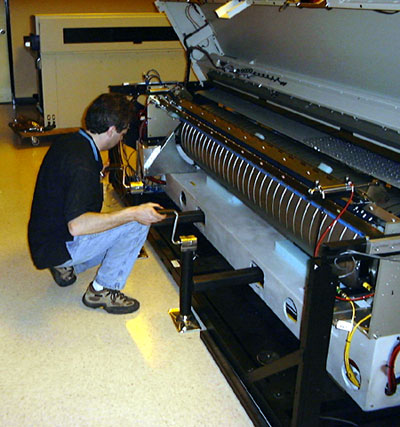
- Place the lifting bars (#56-3266) through the square holes in the engine casting.
- Check that the hose tray is up out of the way of the lifting bars.
- Slide the lifting jacks into the tube ends. Make sure the jacks go in all the way.
Raise the Trendsetter VLF and install the castors.
- Carefully raise the jacks until the bars are bearing against the top of the engine casting holes at all 4 points.
- Place a wood block (#59-3808) under each corner of the VLF Trendsetter for safety.
- Raise the Trendsetter, alternating between the 4 jacks so that the machine is kept level.
WARNING! Do not let any of the lifting points get significantly higher or lower than the others, as this could twist the frame or cause instability.
- Stop lifting when there is enough room to install the castors and screws.
- Check that the wood blocks are still positioned correctly under the corners of the machine.
- Install the 4 screws holding each castor to the Trendsetter VLF frame.
Using jacks to raise and lower the Trendsetter VLF
Lower the Trendsetter VLF onto the castors and remove the jacks.
Move the Trendsetter VLF to its new location.
Install the adjustable feet and set the initial height.
- Lay on the floor, reach under the Trendsetter VLF, remove the retainer screw and the foot pad.
- Remove the foot spacer.
- Lift the new foot into the frame and install the retainer nut.
- Turn the foot up until it stops, then turn it down 2 full rotations.
- Repeat for the other 2 feet.
Remove the hood.
- Open the hood.
- Disconnect the p-door cables and airlines from the Trendsetter VLF and the strut.
- While supporting the hood, remove the retaining clips and the strut.
- Lower the hood.
- Open the p-door.
- Raise the table.
- Remove the hood pivot shoulder bolts and spacers.
- With a help of another person, lift and remove the hood.
- Press the latch
- Lift the hood up and away from the table. Be careful of the p-door.
- Place the hood well out of the way.
Dismantle the table.
- Raise the table.
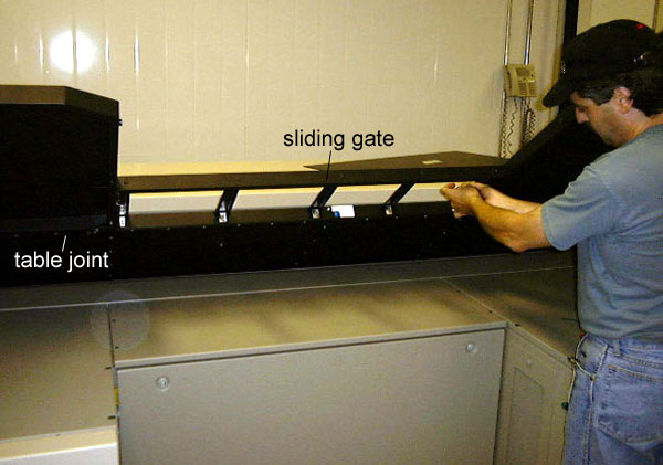
- Remove the 5 sets of capscrews and brackets holding the sliding gate.
- Pull the sliding gate out so that the hole in the metal arm on each side lines up with the screw head underneath. Using a 2.5mm hex key, remove the 2 buttonhead screws.
- Using 2.5mm and 3mm hex keys, loosen all the M3 and M4 capscrews along the table joint, but do not remove them yet. It may be difficult to loosen some of them because of the Loctite.
Removing the screws along the table joint Note: If a screw breaks off, try applying pressure from behind the bracket while unscrewing it. If that doesn’t work, use a hacksaw to remove the screwhead.
- Using a 3 mm hex key, remove and discard the 6 screws holding each wing (3 underneath and 3 facing you). Remove and discard the wings.
- Pull the sliding gate off and discard it.
Replace the user interface.
- Raise the table.
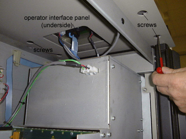
- Using a 3mm hex key, remove the 4 M4x14 screws and washers from underneath the operator interface panel and discard them. The innermost screw may be difficult to remove.
Removing the operator interface panel.
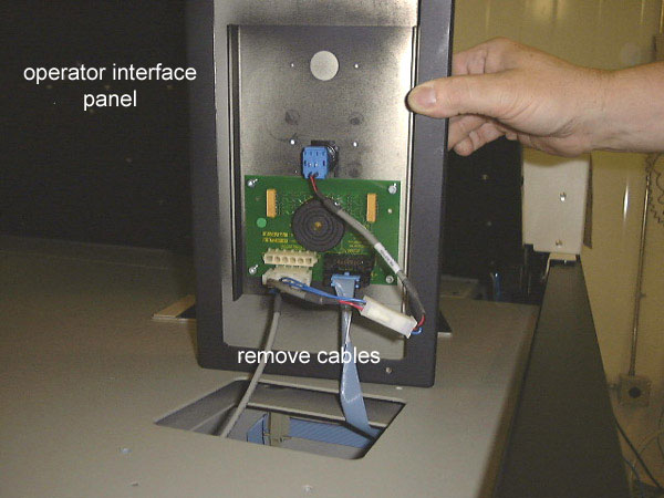
- Disconnect the cables from the operator interface panel.
Underside of operator interface panel - Remove and discard the panel.
- Wipe the surfaces all around the hole with isopropyl alcohol or similar cleaner. Let it dry.
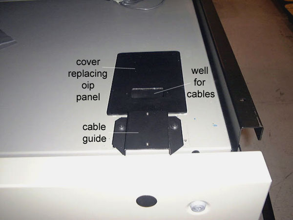
- Insert the bulkhead cable ends into the holes in the well on the new cover that is provided.
- Press the cover down in place over the hole. It must be set back 95mm (3.7") from the edge of the panel so as not to interfere with the mounting bracket for the guard rail.
- Check that the panel is in position and that the adhesive tape adheres well.
Cover in place over old location of operator interface panel
Install the arborite table upgrade panels.
- Lower the table.
- Have a helper hold the table down while you place the wooden table locking block (90-0194) in position beneath the counterweight. The slot in the block fits over the vertical flange on the bottom frame.
- Attach the 3 table drill fixtures (92-0366 left, 92-0367 center, 92-0368 right).
- Drill all 32 pilot holes using a 3mm bit.
- Remove the drill fixtures.
- Enlarge all the holes to 6.3mm diameter.
- Deburr all the holes.
- Clean the table surface and surrounding area.
- Place a 5mm bead of RTV sealant around the 2 left sets of vacuum ports.
- Place panel A onto the table. Align the retainer holes and insert the retaining darts.
- Place the other 3 panels, one at a time. Align the retainer holes and insert the retaining darts.
- Press firmly around the vacuum ports.
Replace the table leading edge.
- Remove the 8 screws and washers.
- Remove the leading edge and place it beside the old hood, well out of the way.
- Place the new leading edge in the uppermost position and install all 8 screws and washers.
- Tighten all fasteners.
To adjust the leading edge:
- place a 12" ruler on the table panel.
- extend the ruler over the leading edge.
- adjust the leading edge to be flush with the table panel.
- adjust, using your hands to lightly push or pull on the leading edge.
- Tighten the retaining screws.
Install the counterweight upgrade.
- Raise and support the table.
- Remove the old counterweight by removing its 4 screws.
- Install the new counterweight, using 4 screws with washers.
- Install the counterweight addition and the counterweight bracket, using 4 screws with washers.
- Tighten all fasteners.
Install the table extension assembly.
- Raise the table.
- Rotate the vacuum selection switch to the vertical position.
- With a helper, lift the table extension up to the Trendsetter VLF table.
- Slide the extension over the two extended rails and onto the lower flange.
- Install all of the fasteners along the adjoining faces.
- Install the screws, washers, and nuts attaching the internal ribs.
- Carefully lower the table.
- Place the filler strip inside the groove on the table surface and press towards the front edge.
- Install the thin black UHMW tape along the groove on top of the filler strip.
Starting at one end of the groove and leaving 100mm of tape extended off the edge of the table, peel the backing off and press the tape into the center of the groove. Progress gradually along the groove to the other side of the table. Continue pressing the tape down the side and underneath the table. Go back over all of the tape slowly and ensure that it is pressed in completely onto the filler strip and the panels.
Note: If any of the tape gets outside the groove, onto the table surface, trim the excess with a sharp knife and a steel straight edge.- Prepare the table struts.
- Raise the table.
- Remove the 3 black plastic caps from each strut.
- Attach the table strut drill fixture (92-0213) to one of the struts.
- Check the orientation. Look for the top and front markings.
- Drill the 3 holes with a 3mm bit.
- Remove the drill fixture.
- Enlarge the holes to 4.2mm.
- Tap the 3 holes to M5.
- Repeat for the other strut.
- Install the external ribs.
- Hold the external rib in position and install the six screws, lock washers, and large flat washers.
Do not over-tighten the fasteners yet.
- place a cassette rail on top of the table above the rib to be adjusted.
- loosen all 6 screws for the external ribs or 1 screw/nut for the internal ribs.
- press up at the front table edge until the table surface is flat to the cassette rail.
- tighten the rib fasteners.
- repeat for the other 3 ribs.
- Remove the cassette rail.
- Tighten all fasteners on the table connection.
- Install the 4 adjustable bumpers. Position the lock nuts on the inside of the table flanges, as required.
- Lower the table.
- Adjust the 4 adjustable bumpers under the table so that they ALL touch the top panels evenly.
- Connect the cable to the safety loops.
- Raise the table
- Route the cables and hoses along the table connection flange, under the external rib and down the strut - use tie wraps as required.
- Route the drop leaf cable (10-4355) along the bottom cable track toward the front end and into the power box.
- Connect the 2 cable connectors to the other cables (they will be installed later).
Position the Trendsetter VLF in its approximate location according to
the floor layout (±12mm).
Align the Trendsetter VLF to the system centerline laser.
- Turn on the laser plane. Recheck that the laser is still in position, and is level.
- Check the centerline reference marks at both ends of the table.
- Roll the machine until the laser touches both edges of the centerline marks (one on the table edge and one on the table fixture).
- Turn off the laser plane.
Attach the table fixture (#92-0369) to the table edge on the cassette
side, then level the fixture (SCU installation only).
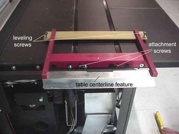
See the drawing: Superjig table fixture
Table fixture (attached to pick side of table)
- Check that the table is down.
- Place the table fixture on top of the table.
- Set the height of the fixture's pivot.
For a Table Left Side pick, rotate the pivot fully clockwise.
For a Table Right Side pick, rotate the pivot fully counter-clockwise.- Place the retainer below the table (newer tables have pem-nuts installed and do not require the retainer).
- Loosely fasten the screws through the table edge (you may want to open the p-door and raise the table to make this task easier without the retainer).
- lower the table
- calibrate the digital level
- turn it on and let the display settle
- Press the Calibration button. 'cal1' will appear on the display.
- Wait a few seconds till the display has settled again.
- Turn the level around 180° and press the Calibration button again. 'cal2' will appear on the display.
- Wait a few seconds till the display has settled again.
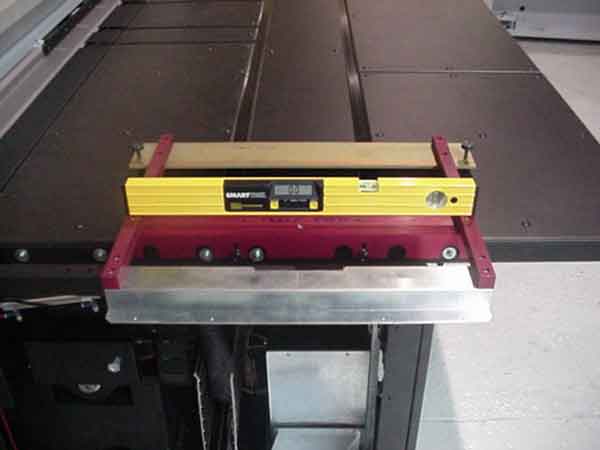
- place the calibrated digital level on the side bar of the fixture, then across the front and rear bars simultaneously
- rotate the leveling screws to adjust the level in both axes to 0° ±0.1°.
Leveling the table fixture
- Tighten the retaining screws.
Position the floor plate (SCU installations only).Note: If the floor plate has been shipped in pieces, re-assemble it by following the instructions in Assembling the Floor Plate.
- Slide the floor plate under the Trendsetter VLF.
- Attach the floor plate alignment fixture (#92-0371) to the table fixture.
See the drawing: Superjig floor fixture- Suspend the plumb-bobs (#90-1125) from the floor plate fixture so they hang just above the floor plate.
- Align the holes in the floor plate under each of the plumb-bob tips. Use a mallet, if needed, to bump the floor plate into position. Placement doesn't have to be exact as further adjustments will be made after the castors are removed.
Positioning the floor plate
Position the 4 lifting jacks (92-0084). See Step 4.
Place the white plastic slide plates (57-8573) under each jack
Raise the Trendsetter VLF and remove the castors. See Step 5.
Lower the Trendsetter VLF.
- Check the position of the floor plate (SCU installations only).
- Make sure that the power box and fan box pucks (pod feet) are not resting on the ground. If they are, raise the Trendsetter VLF using the jacks and rotate the adjustable feet down (1 full rotation = 7 mm height).
- Lower the jacks until the lifting bars are no longer touching the engine casting.
Note: Do not remove the jacks and lifting bars.
Check that the engine is level.
- Place the calibrated digital level (#90-1150) along the casting under the drum and take a reading. It should be 0° ± 0.1°.
- Rotate it 90° and place it on a motor plate beside the drum. You may need to open the hood to place the level. Be careful of the p-door. Take a reading. It should be 0° ± 0.1°.
- Using the adjustable foot wrench, rotate the appropriate adjustable foot in the direction of least deflection
- Recheck the engine level
Recheck the centerline position. For SCU installations only, also
recheck the floor plate position.
To
adjust the alignment of the Trendsetter VLF:
Remove the table fixture plumb bobs and floor plate fixture (SCU
installations only).
Adjust the table to the drum.
- Connect the Trendsetter VLF to AC power.
- Connect the workstation or a laptop to the diagnostic port.
- Connect the shop air supply to the Trendsetter VLF.
- Follow the table alignment procedure (73-3257B)
Install the counterweight dampers.
- Attach both damper drill fixtures (92-0389lower and 92-0390 upper).
- Drill 4 pilot holes with a 3mm bit.
- Remove both drill fixtures.
- Enlarge all holes to 7mm diameter.
- Deburr all holes.
- Install both damper assemblies and tighten all fasteners.
- loosen the large lock nuts.
- rotate the damper until there is 4mm of shaft visible when the table is pressing on it.
- tighten the lock nuts.
- loosen the set screw on the side of the cap.
- rotate the cap slightly.
- test the damper with your hand.
- adjust the cap until the required dampening is achieved.
- test by raising and lowering the table and adjust as required.
- tighten the set screw.
Check that the table is level at both ends. It should be 0° ± 0.5°.
Table levelness is most important at the cassette end, where the pick
happens.
Adjust the table to 0° on the pick side. If the conveyor side of
the table is more than ±0.5°, then adjust the whole table until the
conveyor side is ±0.5°.
To
adjust the table level:
WARNING! Do not tilt the Trendsetter VLF from side to side.
Check the table sensors.
- Raise the table by typing "table up".
- Check the sensor by typing "table".
- Adjust the sensors until 'table up' is true.
- Repeat for "table down".
- Tighten all fasteners.
Re-attach the table fixture (92-0369) to the table edge on the cassette
side and level the fixture. See Step 17.
Recheck that the Trendsetter VLF is aligned to the system centerline
laser.
- Turn on the laser plane.
- Check the reference marks.
- Roll the machine until the laser touches both edges of the centerline marks (one on the table edge and one on the table fixture).
- Turn off the laser plane.
Adjust the power box and fan box pucks (pod feet).
WARNING! Do not lower the pucks further or the frame will twist.
Remove the jacks, sliding plates, and lifting bars.
Lower the hose tray to its lowest position.
Upgrade the lower frame.
- Attach the lower frame drill fixture (92-0396) to the lower frame on the cassette side.
- Drill the 10 pilot holes using a 3mm drill bit.
- Remove the drill fixture.
- Enlarge all of the holes to 7mm in diameter with the drill.
- Enlarge holes A,C,D, and H with a 9.5mm bit.
- Use the 19mm (3/4") cabinet punch in holes C,D, and H.
- Use the 22mm (7/8") cabinet punch in hole A.
- Use the 38mm (1.5") cabinet punch in holes C and D.
- Use the 51mm (2") cabinet punch in hole H.
- Apply a strip of 50mm wide masking tape to the frame between holes C and D.
- Cut along both edges of the tape to create a slot, using the electric jigsaw with a metal cutting blade.
- Deburr all openings.
- Install the 2 frame cover plates.
- Attach the lower frame drill fixture (92-0397) to the lower frame on the conveyor side.
- Drill the 4 pilot holes using a 3mm drill bit.
- Remove the drill fixture.
- Enlarge all of the holes to 7mm in diameter with the drill.
- Enlarge holes L and N with a 9.5mm bit. Note: Hole N is the first from the rear and is used with the L-conveyor only.
- Use the 19mm (3/4") cabinet punch in hole L.
- Use the 22mm (7/8") cabinet punch in hole N.
- Use the 38mm (1.5") cabinet punch in hole L.
- Deburr all openings.
- Install the frame cover plate over hole L.
Upgrade the upper frame (B020-B275 only)
- Remove the top cover from the upper frame by removing the 4 nuts from underneath.
- Attach the support arm drill fixture (92-0391) to the top of the upper frame.
- Drill the 11 pilot holes using a 3mm drill bit.
- Remove the drill fixture.
- Enlarge the 2 marked holes to 6mm in diameter with the drill.
- Enlarge the other 9 holes to 10mm.
- Deburr all edges.
- Repeat for the other side of the frame.
Install the pneumatic upgrades:
- All the fitting and hose pieces should already be completely assembled. Refer to the above drawing for assembly details.
- Remove the threaded fitting from the exit of the regulator assembly.
- Install the new fitting (55-0196) into the regulator.
- Insert the Autoloader hose assembly into the fitting.
- Trim the TSV line (5/16" tube) and connect it to the new hose assembly.
- Route the 1/2" hose across the floor of the frame along the left side rail into the rear frame rail.
- Remove the jam nut from the bulkhead fitting (55-1055), insert fitting into the 22mm hole in the frame side rail, tighten the jam nut and connect the hose assembly. Repeat on the other side of the frame. Both bulkhead fittings must have 3/8" plugs (55-1058) installed.
- The Y fitting closest to the conveyer must have a 1/2" plug (55-0595) installed.
- Tuck the excess hose neatly under the frame rails - use tie wraps as required.
- Close the Autoloader shut-off valve. Do not open until the picker and track has been installed.
Part B - Table vacuum improvement kit, including the three actuators for the Y-axis gripper and table cup functions.
Manifold Bracket assembly drawing
- Turn off the air supply to the whole Trendsetter.
- Remove the second and third screws from the bottom along the left edge of the engine clamp plate.
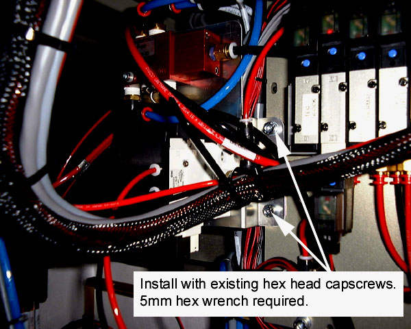
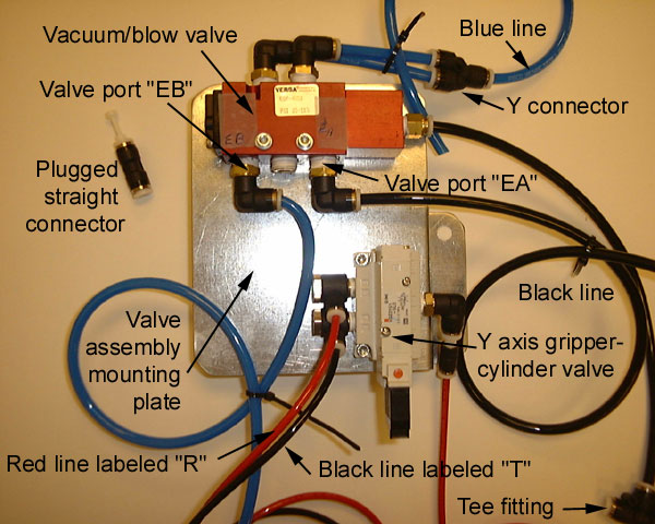
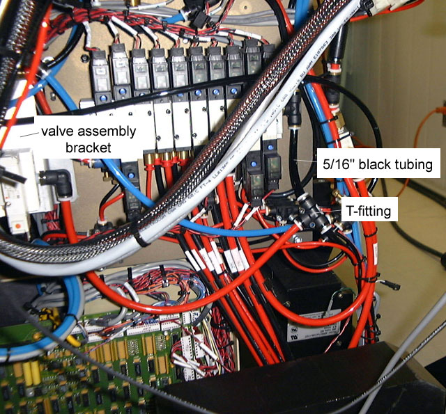
- Attach the valve assembly bracket using the two screw holes from Step 2.
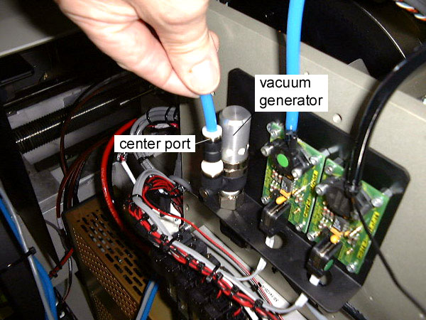
Installing the valve assembly bracket - Disconnect the ¼" O.D. blue tubing from the center port of the vacuum generator.
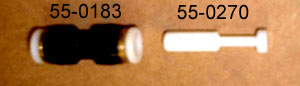
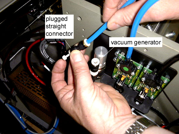
Disconnecting tubing from vacuum generator. - Seal the end of the tube disconnected in Step 3 with the plugged straight connector assembly.

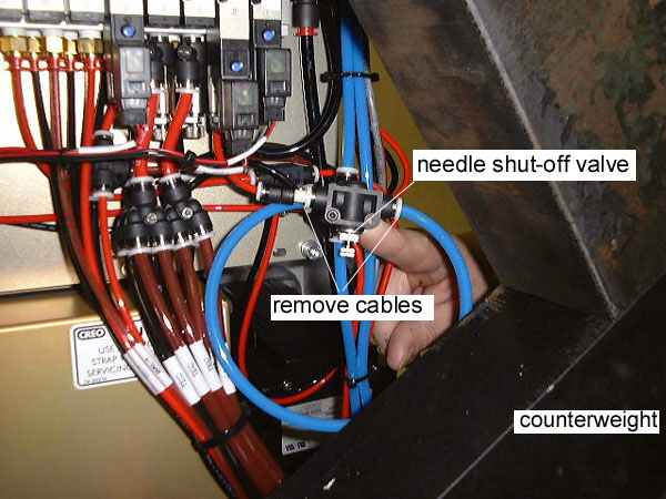
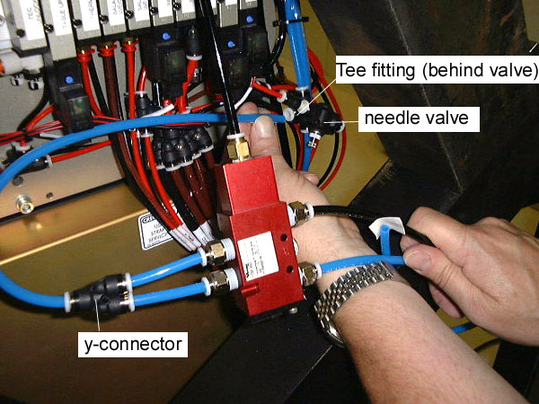
Straight connector and plugAttaching the straight connector - Locate the free-floating needle shut-off valve that has a T-fitting attached behind it with a single through bolt.
Location of needle shut-off valve - Disconnect both ends of the short loop of blue tubing (the end connected to the T-fitting and the end connected to one side of the needle valve).
- Open the needle valve fully by loosening the knurled jamb nut found on the valve stem and rotating the valve spindle fully counterclockwise until it stops rotating.
- Retighten the knurled jamb nut.
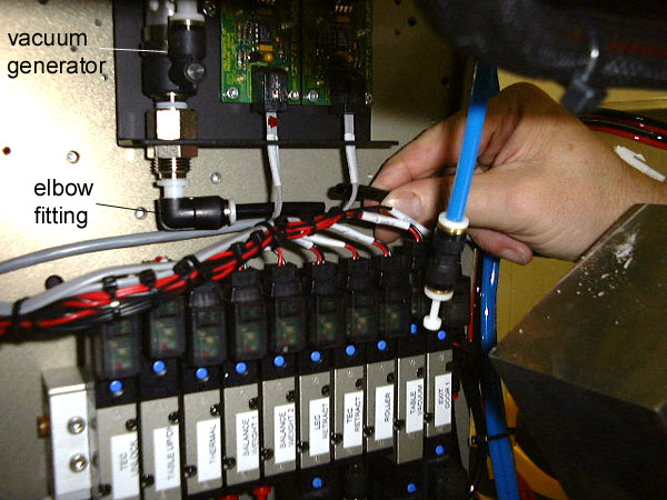
- Locate the elbow fitting at the bottom of the vacuum generator.
- Cut the black tubing approximately 25mm from the vacuum generator elbow fitting and install the T-fitting of the black hose from the new valve assembly.
Valve assembly Installed T-fitting (valve assembly is attached)
- Connect the blue line that comes from the valve port labeled "EB" on the valve assembly to the center port of the vacuum generator (shown in Disconnecting tubing).
- Connect the blue line that comes from the Y-connector on the valve assembly to the open port on the T-fitting of the free floating assembly directly behind the needle valve.
Attaching the y-connector hose of the valve assembly - Connect the black line that comes from the valve port labeled "EA" on the valve assembly to the open port on the needle valve.
- Attach the red gripper actuator hose from the valve assembly bracket to the connector labeled "R" on the back of the P-door (this hose is no longer used and should be plugged).
- Attach the black hose from the gripper actuator on the valve assembly bracket to the connector labeled "T" on the back of the P-door.
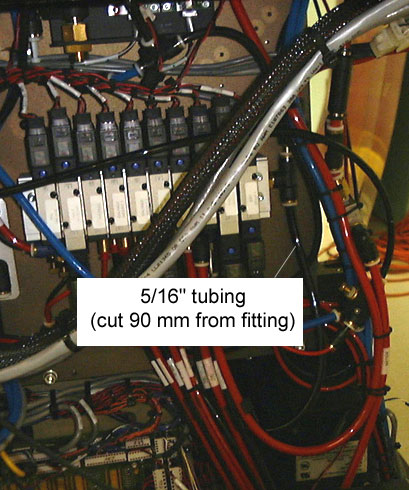
- Locate the 5/16" tube "T" that exits from the rear of the main valve manifold (the manifold that mounts the 16 solenoid-operated directional control valves). The "T" fitting exits from the port labeled "P" on the rear of the manifold.
Location of 5/16" black tubing
- Cut the 5/16" tube "T" approximately 170mm away from where it exits the bottom of the fitting.
- Insert the 5/16" tube "T" from the valve assembly, splicing the ends of the cut tubing together.
5/16" black tubing cut and inserted into T-fitting
- Tidy up the cabling so that it doesn't interfere with the movement of the counterweight or the P-door.
- Secure the valve assembly and its tubing to the existing hose and cable bundle. Make sure that the hoses are adequately secured to prevent any binding when the table is moved.
Install the electrical upgrades.
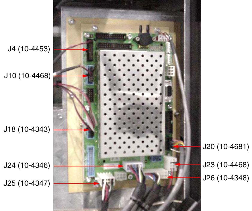 |
Genine 0 electrical connections |
- Turn OFF all power and unplug the TS from the power supply.
- The electrical upgrade kit includes 1 board (Genine 0), 14 cables (minimum) with 41 connections and the mounting brackets required to attach everything to the TS.
- Many of the cables will be routed into the TS power box, open the cable trays and loosen the cable clamps at both exits.
- Access the front cable tray, behind the center panel and remove the cap from the tray.
- The right side cable tray starts behind the power box and goes below the counterweight.
- Working inside the power box, attach the mounting bracket for Genine 0 to the outside of the card cage. Remove the 3 screws that are already installed, position the bracket, and install the 3 screws.
- Attach the Genine board to the bracket - the vacuum sensor must be at the top. Use the 4 flat washers and nylock nuts to secure the board.
Note: The installer MUST be wearing an antistatic strap before removing the board from the protective bag.- Install cable #10-4346 from the left frame bulkhead (encoder side) to the power box. · Insert the cable into the power box, through the hole in the lower left corner behind the power supply. Route it along the bottom cable tray, under the card cage and up to Genine 0. · Attach the connector (GEN0.J24) to terminal J24 on Genine 0. · The connector (AL SAFETY) will connect to connector (SAFETY EXP) on cable #10-4348 after it is installed. · Route the other end of the cable along the front TS cable tray to the left frame rail and out of the large rectangular opening near the back. Allow 100-150mm of cable to extend from the frame opening. · Do not tie wrap the cable until ALL cables have been installed.
- Install cable #10-4348 from the right frame bulkhead (motor side) to the power box. · Insert the cable into the power box, through the opening in the lower right corner. Route it under the card cage and up to Genine 0. · Attach the connector (GEN0 J26) to terminal J26 on Genine 0. · Attach the connector (SAFETY EXP) to connector (AL SAFETY) on cable #10-4346. · Attach the connector (TABLE LEAF) to connector (DROP LEAF, AL SAFETY) on cable #10-4355 that was installed with the new table assembly. · The last connector (GUARDRAIL) will be connected to cable #10-4468 after it is installed. · Route the other end of the cable along the cable track and out of the opening in the frame. Let it extend 100-150mm. · Do not tie wrap the cable until ALL cables have been installed.
- Install cable #10-4681 from the p-door to the power box. · Insert the cable into the power box, through the opening in the lower right corner. Route it under the card cage and up to Genine 0. · Attach the connector (GEN0 J20) to terminal J20 on Genine 0. · Route the other end of the cable along the cable track, for a short distance, and then up the frame/strut to the p-door. The connectors will attach to the y-axis home and away sensors after the new hood is installed. · Do not tie wrap the cable until ALL cables have been installed.
- Install cable #10-4347 from the p-door to the power box. · Insert the cable into the power box, through the opening in the lower right corner. Route it under the card cage and up to Genine 0. · Attach the connector (GEN0 J25) to terminal J25 on Genine 0. · Route the other end of the cable along the cable track, for a short distance, and then up the frame and hood strut to the p-door. · The connector will attach to the y-axis drive motor after the new hood is installed. · Do not tie wrap the cable until ALL cables have been installed.
- Install cable #10-4343 from the actuator manifold to the power box. · Insert the cable into the power box, through the opening in the lower right corner. Route it under the card cage and up to Genine 0. · Attach the connector (GEN0 J18) to terminal J18 on Genine 0. · Route the other end of the cable along the cable track, for a short distance, and then up the frame to the air manifold behind the counterweight. · Attach the connector (Y-AXIS) to the y-axis gripper actuator. · Do not tie wrap the cable until ALL cables have been installed.
- Install cable #10-4453 from the engine satellite board to the power box. · Insert the cable into the power box, through the opening in the lower right corner. Route it under the card cage and up to Genine 0. · Attach the connector (GEN0 J4) to terminal J4 on Genine 0. · Route the other end of the cable along the cable track to the engine satellite board, behind the counterweight. · Attach the connector (SAT J30) to terminal J30 on the satellite board. · Do not tie wrap the cable until ALL cables have been installed.
- Install cable #10-4451 from the engine satellite board to the power box. · Insert the cable into the power box, through the opening in the lower right corner. Route it under the card cage and up to the top bulkhead plate (where the user interface used to be). · Attach the connector (GUARD RAIL) to the top bulkhead plate. A cable from the guard rail assembly will be connected after the guard rail is installed. · Route the other end of the cable along the cable track to the engine satellite board, behind the counterweight. · Attach the connector (SAT J1) to the J1 terminal on the satellite board. Remove the blue ribbon cable #10-3537A from terminal J1 first. · The third connector (TRACK LIGHTS) will attach to cable #10-4380 after it is installed. · Do not tie wrap the cable until ALL cables have been installed.
- Install cable #10-4468 inside the power box. · Attach the connector (GUARD RAIL) to the top bulkhead plate (where the user interface used to be). A cable from the guard rail assembly will be attached after the guard rail is installed. · Route the other end of the cable down to Genine 0. · Attach the white 8 pin connector (GEN J23) to terminal J23 on Genine 0 and attach the black 14 pin connector (GEN J10) to terminal J10. · Route the other two connectors down to the power box floor. · Attach the connector (GUARD RAIL, AL SAFETY) to connector (GUARD RAIL, AL SAFETY) on cable #10-4348. · The last connector (GUARD RAIL, VLF SAFETY) will attach to cable #10-4449 after it is installed. · Do not tie wrap the cable until ALL cables have been installed.
- Install cable #10-4449 inside the power box. · Attach the connector (J4) to terminal J4 on the Registration Table Safety Electronics board that is mounted at the back of the power box. · Route the other three connectors down to the power box floor. · Attach the connector (GUARD RAIL) to connector (GUARD RAIL, VLF SAFETY) on cable #10-4468. · Attach the connector (DROP LEAF) to connector (DROP LEAF, VLF SAFETY) on cable #10-4355 that was installed with the new table assembly. · The last connector (CONV PANEL) will attach to cable #10-4603 after it is installed. · Do not tie wrap the cable until ALL cables have been installed.
- Install cable #10-4603 from the conveyor interface switch to the power box. · Attach the connector (CONV PNL) to cable #10-4449 at the bottom of the power box. · When the conveyor is going to be on the right hand side of the TS, route the other end of the cable out of the top, right side of the power box. Let the connectors extend about 400mm past the frame and tie wrap the extra cable. · When the conveyor is going to be on the left hand side of the TS, route the cable out of the lower left corner of the power box, along the front cable tray and up to the top left frame rail. · The connectors will attach to the switch after the conveyor interface is installed. · Do not tie wrap the cable until ALL cables have been installed.
- Install cable #10-4344 from the frame bulkhead to the power box. · Attach one of the connectors to the serial port (LASER CH2) on the Backplane board inside the power box. · When the cassette is going to be on the right hand side of the TS, route the other end of the cable out of the lower, right corner of the power box, under the cardcage and along the cable tray to the 50mm hole in the lower frame rail. · When the cassette is going to be on the left hand side of the TS, route the cable out of the lower left corner of the power box and along the front cable tray. · Attach the connector to cable #10-4345 and continue routing the cable along the front cable tray and along the left frame rail to the 50mm hole. · Attach bracket #57-7614 to the connector, then attach the bracket to the inside of the frame rail. · Do not tie wrap the cable until ALL cables have been installed.
- Install cable #10-4380 from the engine satellite board to both track support arms. · Attach the connector (SAT BRD) to connector (TRK LGHT) on cable #10-4451 near the engine satellite board. · Route the cable along the inside rear frame rail and up both rear frame uprights. · The cable will route inside each track support arm, along the track to the lights in the track skins after they are installed.
- Install cable #10-4378 from the lower frame bulkhead to both track support arms. · Let the bulkhead connector extend from the frame 100-150mm. · Route the cable along the inside rear frame rail and up both rear frame uprights. · The cable will route inside each track support arm and attach to the x-axis home and away sensors after they are installed.
- Install cable #10-4381 from the lower frame bulkhead to the nearest track support arm. · Let the bulkhead connector extend from the frame 100-150mm. · Route the cable along the inside frame rail and up the rear frame upright. · The cable will route inside the track support arm and attach to the x-axis motor after they are installed.
- Install cable #10-4390 from the lower frame bulkhead to the nearest track support arm. · Let the bulkhead connector extend from the frame 100-150mm. · Route the cable along the inside frame rail and up the rear frame upright. · The cable will route inside the track support arm and attach to the track cable after they are installed.
- Install cable #10-4397 from the lower frame bulkhead to the nearest track support arm. · Let the bulkhead connector extend from the frame 100-150mm. · Route the cable along the inside frame rail and up the rear frame upright. · The cable will route inside the track support arm and attach to the x-axis safe home and safe away sensors after they are installed.
- Attach the two bulkhead brackets #57-7409 to the lower frame rails. Y. Tie wrap the extended cables to the bulkhead brackets, then neatly tuck the cables away. Close all of the cable trays and tie wrap all the cables.
Install the hood assembly.
- Lower the table.
- With a helper, lift the hood assembly out of the crate.
- Position the new hood on top of the upper frame, behind the table. Align the pivot holes to the frame.
- Open the p-door.
- Raise the table.
- Install the shoulder bolts and spacers on both sides.
- Lower the table.
- Raise the hood.
- Attach the strut and insert the retaining clips.
- Route the cables and hoses along the strut and cable bundle.
- Connect the cables to the harness.
- Connect the hoses to the actuators.
- Install the cable ties as required.
Check the angle of the p-door.To
adjust the p-door angle:
Check the plate drop.See also the full Trendsetter VLF Plate Door Adjustment
To
adjust the plate stop:
Set the y-axis home position.
Install the track support arms.
- The track support arms will require adjustments after the picker has been installed. Use the following adjustment procedures to adjust the track support arms.
- horizontal - top through bolts
- vertical
- rotational
- aligned to each other