Home | Contact Us | Submit Troubleshooting Info | Search | Help
Output | Software Solutions | Proofing | Color, Screening and Calibration | Scanning | Digital Photography | Consumables | POS
Home | Contact Us | Submit Troubleshooting Info | Search | Help
Output | Software Solutions | Proofing | Color, Screening and Calibration | Scanning | Digital Photography | Consumables | POS
Objectives:
Before the track and picker assemblies are installed:
Refer to the drawing: Track assembly
 Prepare the Trendsetter VLF for track mounting.
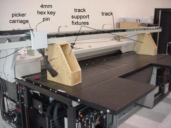
- Place the 2 track support fixtures (#92-0198B) on the table, one at each end.
- Undo the cable ties that secure the cables to the track support arms and move the cables out of the way in preparation of installing the track onto the support arms.
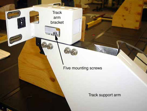
- Attach the track arm brackets to the support arms with five bolts on each side (the long screw goes in the middle).
Track support arm brackets
Lift the track onto the fixtures.
- With a helper, lift or roll the track crate and place it in front of the Trendsetter VLF.
Tip: Place the track mounting screws on the hood so that they are accessible when mounting the track.- Lift the track out of the crate and place it on the fixtures. Position the track and fixtures close to the support arms.
Warning: Check that the drive belt is not being pinched on the fixtures.- Route the cable and hose from the track into the support arm.
Track mounted on jigs
Move the track onto the support arms and fasten.
- With a helper, lift the track from the fixtures onto the support arms.
- Install all fasteners securely.
- Connect the hose to the supply fitting near the bottom of the VLF Trendsetter frame at the rear.
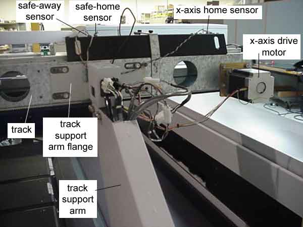
- Connect the cables at the top of the support arms.
- Remove the tie strap attached to the drive belt.
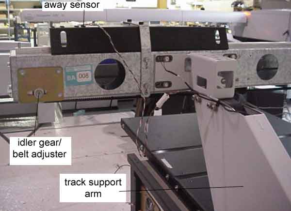
- Loosen the tension on the idler gear.
Note: Leave the foam in place on the track ends. It is there for your safety
Cabling from support arm at motor end of track Cabling from support arm at conveyor end of track
Install the drive motor. See photo above.
- Connect the motor ground cable using a star washer.
- Tension the belt lightly with the idler gear. The belt should be one half inch from the bottom of the middle of the track. Tip: This is easier to do if you remove the track end-plate.
Note: The idler gear has a bearing inside. Do not over tighten it.- Tighten all fasteners.
- Connect the motor cable and sensor cables - feed the cables through the brackets where possible.
Remove the track support fixtures.
Prepare the picker for mounting.
- Check that the protective foam pad is still attached to the bottom of the picker.
- Place the picker on the table, near the center. Open the drop-leaf gate for better access.
- Carefully remove the two picker skins.
- Remove the 4mm pin that secures the picker carriage to the track.
- Slide the picker carriage close to the picker.
- Insert the cable and hoses into the picker arm.
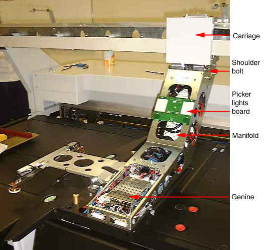
- Connect the two hoses to the two manifold hoses. Temporarily remove the picker lights board to get access to the manifold.
- Connect the cable to the Genine board - J24 SCON2. Connect the ground wire to the genine's corner mounting screw.
- Route the cables and hoses in the arm so that they do not interfere with any connections.
Picker components
Lift the picker into position.
- Lift the picker up to the picker carriage.
Note: Handle the picker with care!
- Securely tighten the two shoulder bolts that attach the picker to the carriage (this will require an imperial Allen key).
- On the left side of the Trendsetter, temporarily plug the air supply fitting that is for the garage or MCU.
- Turn the AL air supply shut-off valve ON. The p-cup arm and the pusher fingers will lift up.
WARNING! To move the picker by hand, never push or pull the picker body or arm. Push or pull on the picker carriage or the drive belt.
- Remove the protective foam pad from the bottom of the picker.
Set the picker 'safe' position.
- Lift the picker up and over the table jig and move it to the left edge of the table where the table jig is attached.
- Lock the carriage by placing a 4mm pin (hex key) through the hole in the picker carriage and into the hole in the track.
- Check that the pusher edge of the picker body is within the marks on the picker fixture.
See the drawing: Superjig table fixtureTo adjust the picker 'safe' position:
- Loosen the track support arm flange-to-track fasteners, 4 on each side.
- Slide the track in the appropriate direction by hitting the support arm with a soft, heavy (dead-blow) hammer in the opposite direction. Don't hit the track itself.
- Tighten all 8 fasteners.
- Recheck the picker 'safe' position.
Check the levelness of the picker. It should be 0° ±0.1°.
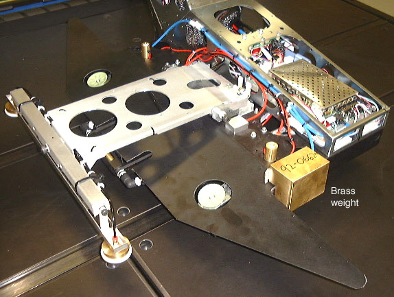
- Attach the brass weight to the picker to simulate the weight of the picker skins.
Brass weight
- Place the calibrated digital spirit level across the top of the lift arm bracket on the picker body and take a reading.
- Loosen the five fasteners that hold the left track support arm to the Trendsetter.
- Rotate the adjustment screws until the angle is correct (located on the underside of the support arm).
- Tighten the track support arm fasteners.
- Recheck the picker 'safe' position. See Step 9.
Check the picker height.
- Check that the bottom edge of the 'push' side of the picker body shows through the "window" formed by the two tabs on the picker fixture.
- Loosen the track support arm fasteners.
- Rotate the vertical adjustment screws.
- Tighten the support arm fasteners.
Check the picker alignment to the system centerline.
- Check that the system centerline laser fixture is aligned to the reference marks. The laser should touch both edges of the picker body centerline holes.
- Loosen the track support arm fasteners.
- Rotate the horizontal adjustment screw until the picker is aligned.
- Tighten the support arm fasteners.
Move the picker to the conveyor side.
- Remove the 4mm pin from the picker carriage.
- Lift the picker over the table jig and move it to the right side table edge. Make sure the picker body is over the table, and the 'push' side is flush with the table edge.
Check the levelness of the picker and adjust the track support arm as
needed. It should be 0° ±0.1°.
Recheck the picker alignment to the system centerline.
Check that the track is level to 0° ±0.2°.
- Place the calibrated digital spirit level along the top of the track at two locations and take readings.
- Loosen the track support arm fasteners (conveyor side only).
- Rotate the vertical adjustment screws.
- Tighten the track support arm fasteners.
Move the picker back to the cassette side.
Recheck the levelness of the picker. It should be 0° ±0.1°.
Recheck the picker alignment to the system centerline.