Home | Contact Us | Submit Troubleshooting Info | Search | Help
Output | Software Solutions | Proofing | Color, Screening and Calibration | Scanning | Digital Photography | Consumables | POS
Home | Contact Us | Submit Troubleshooting Info | Search | Help
Output | Software Solutions | Proofing | Color, Screening and Calibration | Scanning | Digital Photography | Consumables | POS
For assembly drawings, see the Parts/tools page.
For related procedures, see the Procedures page.
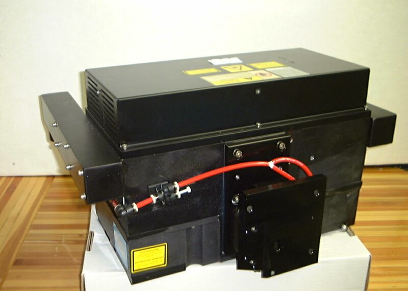
Thermal Head 1.0, air cooled |
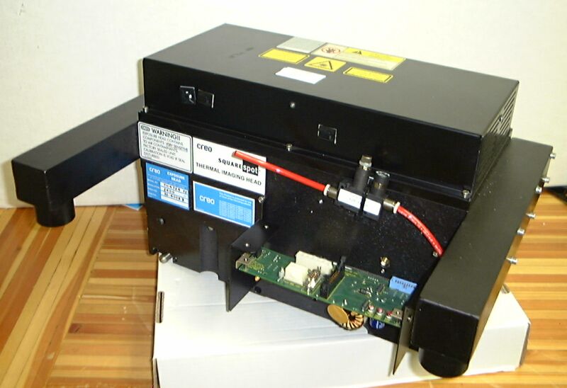
Thermal Head 1.0, air cooled |

Thermal Head 1.7, back side |

Thermal Head 1.7, front side |

Thermal Head 1.7, head connectors: MCE-GMCE |

Thermal Head 1.7, head connectors: MPE |

Thermal Head 1.7, home side mounting details |

Thermal Head 1.7, home side with DHU |
See also Importance of lens cleaning and debris removal.
 Assembly drawings are visual representations of bills of materials (BOMs), labeled with part numbers. They are generally presented with a BOM. That is why, even though they are drawings, they are located on the Parts/tools page.