Home | Contact Us | Submit Troubleshooting Info | Search | Help
Output | Software Solutions | Proofing | Color, Screening and Calibration | Scanning | Digital Photography | Consumables | POS
Home | Contact Us | Submit Troubleshooting Info | Search | Help
Output | Software Solutions | Proofing | Color, Screening and Calibration | Scanning | Digital Photography | Consumables | POS
Time needed: 1.5 hours (Device can be returned to customer within approximately 40 minutes)
Requirements:
Related procedures:
| Print this document | Click the print icon  at the top of the page. |
Print it in landscape format. | |
| Safety | Before you start, make sure you are familiar with all device and laser safety concerns. | For more information see Laser safety information. | |
| External Checks | Action | Look For | Procedure or
Parts |
|---|---|---|---|
| Back up the NVS settings. | In Service Shell, run: NVSDump.spt | N/A | |
| Perform a visual check. | Visually inspect the outside of the head and the surrounding area. |
|
|
| Check the coolant and the coolant reservoir. |
|
|
|
| Check the coolant connector O-rings. | Visually inspect the O-ring on the hose and the O-ring on the head. |
|
|
| Clean the chiller air filter. | Clean the air filter on the front of the chiller. | The air filter in the front of the chiller may be blocked with dust, reducing the effectiveness of the chiller. |
|
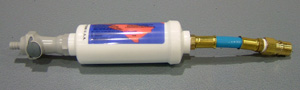
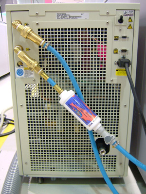
| Replace the external chiller coolant filter. | Replace coolant filter assembly 500-01665A on the rear of chiller. | Failure to replace this filter every 6 months will limit coolant flow, which may cause overheating. |
|
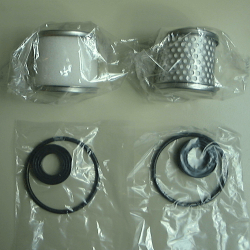
| Replace the air bearing filter on the air manifold. | Replace the filter. Air bearing kit 332-00027 (photo) | N/A |
|
| Check the temperature and voltage levels. |
|
All voltage and temperature levels should be within range. | |
| Check that the head and device are running the latest controlled release. | Check the CR version against the latest released version on TechPlanet. |
If necessary, upgrade to the latest controlled release. | |
| Test the remote connection and configuration functions. | Perform a RAS check: Contact the Response Center (RC) and request that they dial in. | Confirm the connection, passwords, IP addresses, and so on. If any relevant information has changed, notify the RC. | |
| Verify the processor setup. | Ensure the processor meets operating specifications. | Check the setup specifications using the appropriate documentation. | |
| Safety | Warning: Follow all Laser and Mechanical Safety Procedures during the next steps. | ||
| Remove the head from the carriage. | Turn off the device. All laser and mechanical safety procedures must be followed. |
To remove the head from the device you must use the lifting jig. |
|
| Inspect and clean the debris removal nozzle. | Clean the debris removal nozzle. |
Note: It is not possible to clean the debris removal nozzle if the head is on the device. |
Cleaning the Thermal 3 Final Lens and Debris Removal Nozzle |
| Inspect and clean the final lens. | Clean the final lens and surrounding area. You will need the lens cleaning kit (Lens cleaning kit: 04-0012B BOM). |
Note: It is not possible to clean the final lens if the head is on the device. |
|
| Install the head. |
|
|
|
Note: If you are using a laptop, the results will be automatically stored there. You will need to copy them to the workstation.
| Imaging Checks | Action | Look for | Procedure or
Parts |
|---|---|---|---|
| Back up the NVS settings. | In Service Shell, run: NVSDump.spt | N/A | |
Upgrade the head firmware to version 1.04.06. |
|
N/A | |
| Record the image count. |
|
If there is more debris than you would expect, plan to proactively inspect and clean the debris removal system, nozzle, and thermal head final lens more frequently. | |
| Generate a reference plot. |
|
If there are problems with image quality, refer to the appropriate media technical note. Troubleshoot as needed. |
|
| Generate a reference stroke cal. | Create a stroke cal graph. In Service Shell, run: BeamBalance.spt and BeamProfile.spt. |
|
| Script name | Good | Poor/Fail | Notes |
|---|---|---|---|
| BBSProfile.spt | bbsprofile_stuck_pixel.png | BeamBalance.spt | BeamBalance_good.pdf | If you get results that look like failed_1 or failed_2, escalate to your PSS. |