Home | Contact Us | Submit Troubleshooting Info | Search | Help
Output | Software Solutions | Proofing | Color, Screening and Calibration | Scanning | Digital Photography | Consumables | POS
Home | Contact Us | Submit Troubleshooting Info | Search | Help
Output | Software Solutions | Proofing | Color, Screening and Calibration | Scanning | Digital Photography | Consumables | POS
Whisper - SciNet
|
| Item | Quantity | Cat. No. | |
| Ethernet: | |||
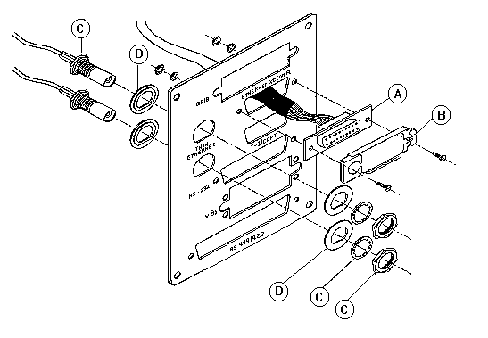
| A. | LANC Internal Cable | 1 | 504E26112 |
| B. | Sliding Lock Retainer | 1 | 203H10048 |
Thin Ethernet: |
|||
| C. | RG 58 BNC/P-BNC cable | 2 | 199B10600 |
| D. | Insulating Washer | 4 | 382S10010 |
CU-II: |
|||
| M. | Comm. Unit Internal Cable | 1 | 504D25077 |
| N. | Bushing | 6 | 383L01550 |
| O. | Phil Screw 3/8" | 4 | 380J01041 |
| P. | Spring Washer | 10 | 382D05000 |
| Q. | Hex Nut | 10 | 381A01000 |
De-Install the Panel
The Communications Panel is already installed in the Whisper 486 cabinet. If there are any cables connected to the panel, unplug them. Unplug any internal communications cable(s) from their board.
Thin Ethernet Precautions:
After disconnecting the Thin Ethernet cables, it is
important to connect the two loose BNC cables together
via a barrel or T-connector, as quickly as possible. This
is necessary to keep the network operational.
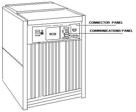
Remove the Communications Panel by unscrewing the four screws on the Connector Panel of the cabinet. If no other communication kits have been installed previously, remove and discard the blank panel which sits behind the Communications Panel.
The two rounded openings labelled "Thin Ethernet" are for the BNC connection to the Thin Ethernet ("Cheapernet") LAN. The slot marked "Ethernet Xceiver" is for the Ethernet connection to network. The four lower slots are for connections to the MPCB Board.
Whisper
486 Cabinet - rear view:
Connecting the Internal Cables From the Board to the Panel
NOTE: Install both Ethernet and Thin Ethernet connectors, even if only one of them is planned to be used. You may need them later.
Install the connectors on the Communications Panel for the Whisper 486 cabinet as follows:
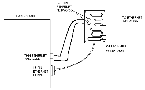
| LAN - Thin Ethernet ("Cheapernet") | Thin
Ethernet connections between nodes are made
through the Communications Panel. Install the
female end of each coaxial cable (199B10600)to
the appropriately marked holes in the
Communications Panel. Connect the male end of
each coaxial cable to the BNC connector on the
LANC Board. NOTE: For LANC Boards which have only one BNC connector, insert a "T" connector. Treat each end of the "T" as a separate BNC connector as described above. |
| LAN - Ethernet | Using the sliding lock retainer and accompanying screws supplied with the kit (203H10048), install the female end of the LANC internal cable (504E26112) in front of the slot labelled "Ethernet" on the Communications Panel. Make sure that the grounding hook is attached to the screw on the Ethernet connector on the back side of the panel. Plug the male end of the LANC internal cable into the 15-pin connector on the LANC Board and lock the lock retainers. |
| LINK | The
Remote Communications kit is supplied with an
internal cable (504D25077) which has a 50-pin
connector on one end. The other end of this cable
splits into four separate connectors. Using the small hardware supplied with the kit, install all four interface connectors (V.35,RS-449/422, RS-232, T1/CEPT) in front of the appropriate slots on Communications Panel. Note that when installing the V.35 connector, remove its metal connector holder, if there is one, in order to allow it to be passed through the panel opening. Plug in the 50-pin connector to the board. |
Re-Install the Panel
Replace the Communications panel on the Connector Panel of the Whisper 486 cabinet.
Connector
Installation for Whisper Cabinet (SciNet/LAN):
Whisper
Connection of LANC Board:
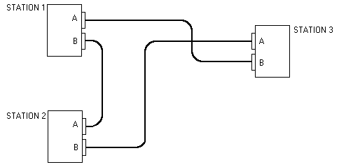
Parts
The LAN and CU-II kits contain the communication board (LANC or MPCB), the cables and small hardware needed for connecting the cables from the board to the Communications Panel.
Below is a list of parts for this procedure.
| Item | Quantity | Cat. No. | |
| Ethernet: | |||
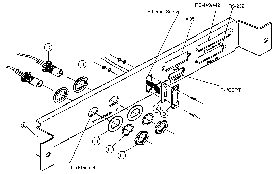
| A. | LANC Internal Cable | 1 | 504E26112 |
| B. | Sliding Lock Retainer | 1 | 203H10048 |
Thin Ethernet: |
|||
| C. | RG 58 BNC/P-BNC cable | 2 | 199B10600 |
| D. | Insulating Washer | 4 | 382S10010 |
Communications Panel Hardware |
|||
| E | Communications Panel | 1 | 284A26435 |
| F | comm panel washer | 2 | 382A13001 |
| G | comm panel tooth | 2 | 382J14010 |
| H | comm panel bolt | 2 | 380J06065 |
I |
Comm. Panel Adaptor |
2 |
290A26377 |
| J | flat washer #8s | 2 | 382A10011 |
| K | Ext. Tooth #8 | 2 | 382J11002 |
| L | Hex Nut #8-32*1/8" | 2 | 381A05002 |
CU-II: |
|||
| M. | Comm. Unit Internal Cable | 1 | 504D25077 |
| N. | Bushing | 6 | 383L01550 |
| O. | Phil Screw 3/8" | 4 | 380J01041 |
| P. | Spring Washer | 10 | 382D05000 |
| Q. | Hex Nut | 10 | 381A01000 |
De-Install the Panel
The
Communicatons Panel (location) on the Whisper Cabinet:
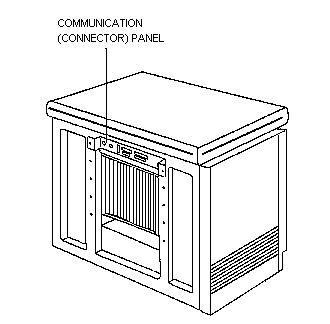
The
Whisper Communications Panel:
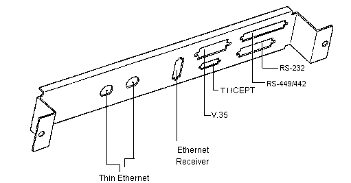
If no other communication kits have been previously installed, use the panel supplied with the kit and proceed to the section below "Install the Connectors."
If the Communication Panel is
already installed in the Whisper cabinet, disconnect all
the cables plugged into the panel.
Thin Ethernet
Precautions:
After disconnecting the Thin Ethernet
cables, it is important to connect the two loose BNC
cables together via a barrel or T-connector, as soon as
possible. This is necessary to keep the network
operational.
Unplug the internal communication cable(s) from their board. Remove the Communications Panel by unscrewing the two screws which connect the panel to the chassis.
The two rounded openings labelled "Thin Ethernet" are for the BNC connection to the Thin Ethernet ("Cheapernet") LAN. The slot marked "Ethernet Xceiver" is for the Ethernet connection to network. The four other slots are for connections to the MPCB Board.
Install the Connectors
| Thin Ethernet ("Cheapernet") | Thin
Ethernet connections between nodes are made
through the Communications Panel. Install the
female end of each coaxial cable (199B10600) to
the appropriately marked holes in the
Communications Panel. Connect the male end of
each coaxial cable to the BNC connector on the
LANC Board. NOTE: For LANC Boards which have only one BNC connector, insert a "T" connector. Treat each end of the "T" as a separate BNC connector as described above. Be sure that the connectors are well insulated so they cannot contact connectors on any other boards. |
| Ethernet | Using
the sliding lock retainer and accompanying screws
supplied with the kit (203H10048), install the
female end of the LANC internal cable (504E26112)
in front of the slot labelled
"Ethernet" on the Communications Panel.
Make sure that the grounding hook is attached to
the screw on the Ethernet connector on the back
side of the panel. Plug the male end of the LANC internal cable into the 15-pin connector on the LANC board and lock the lock retainers. NOTE: Install both Ethernet and Thin Ethernet connectors, even if only one of them is planned to for use. You may need them later |
| SciNet/Link | The
Remote Communications kit is supplied with an
internal cable (504D25077) which has a 50-pin
connector on one end. The other end of this cable
splits into four separate connectors. Using the small hardware supplied with the kit, install all four interface connectors (V.35, RS-449/422, RS-232, T1/CEPT) in front of the appropriate slots on Communications Panel. Remember when installing the V.35 connector, to remove its metal connector holder, if there is one, in order to allow it to be passed through the panel opening. Plug in the 50-pin connector to the board. |
Install the Panel in the Whisper Cabinet
Install the Communications panel to the Whisper cabinet above the main electronics crate.
If your Whisper system is one that has two holes in the top portion of the frame, affix the Communication Panel to the Whisper cabinet frame with two screws.
Installing
the Whisper Communications Panel in a Cabinet with Hole:
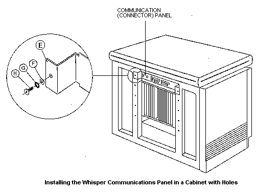
Whisper systems which do not have holes in the chassis frame for connecting the Communication Panel require the additional adapter brackets that are supplied with the kit (Part # 290A26377). Attach the brackets to the Whisper chassis using the screws already located there.
Now, take the Communications panel and align its holes to the bolts which protrude from the brackets. Attach using the washers and nuts supplied.
Installing
Communications Panel with Adapter Brackets:
Parts
The LAN and CU-II kits contain the communication board (LANC or MPCB), the cables and small hardware needed for connecting the cables from the board to the Communications Panel. Note that for micro-type cabinets, the Communications Panel is already installed on the cabinet.
Below is a list of parts for this procedure.
| Item | Quantity | Cat. No. | |
| Ethernet: | |||
| A. | LANC Internal Cable | 1 | 504E26112 |
| B. | Sliding Lock Retainer | 1 | 203H10048 |
CU-II: |
|||
| M. | Comm. Unit Internal Cable | 1 | 504D25077 |
| N. | Bushing | 6 | 383L01550 |
| O. | Phil Screw 3/8" | 4 | 380J01041 |
| P. | Spring Washer | 10 | 382D05000 |
| Q. | Hex Nut | 10 | 381A01000 |
The first step is to access the Communications Panel. To do this, first remove the front power panel by pulling on the four round plastic holders which affix the power panel to the chassis. The Communications Panel is now completely exposed.
If there are any cables connected to the panel, unplug them. Unplug any internal communications cable(s) from their board.
Access the Communications Panel screws by removing the side and top covers of the micro-type cabinet. There are two screws located on each side of the chassis which affix the Communications Panel to the micro cabinet. Remove these four screws and carefully slide the panel in a downward direction until it can be pulled out completely.
There are no connector openings for Thin Ethernet on the panel, since the connections to the network are made directly from the LANC Board. The slot marked "Ethernet Xceiver" is for the Ethernet connection to the LANC Board. There are four other slots for connections to the MPCB Board.
Install the Connectors
Install the connectors on the Communications Panel for the micro cabinet as follows:
| Ethernet | Using the sliding lock retainer and accompanying screws supplied with the kit (203H10048), install the female end of the LANC internal cable (504E26112) in front of the slot labelled "Ethernet" on the Communications Panel. Make sure that the grounding hook is attached to the screw on the Ethernet connector on the back side of the panel. Plug the male end of the LANC internal cable into the 15-pin connector on the LANC Board and lock the lock retainers. |
| Thin Ethernet ("Cheapernet") | There is no connection for Thin Ethernet on the Communications Panel for the micro cabinets as the BNC cables are connected from the LANC Board directly to the network. |
| SciNet/Link | The
Remote Communications kit is supplied with an
internal cable (504D25077) which has a 50-pin
connector on one end. The other end of this cable
splits into four separate connectors. Using the small hardware supplied with the kit, install all four interface connectors (V.35, RS-449/422, RS-232, T1/CEPT) in front of the appropriate slots on Communications Panel. Note that when installing the V.35 connector, you should remove its metal connector holder, if there is one, in order to allow it to be passed through the panel opening. Plug in the 50-pin connector to the board. |
Install the Panel
Re-install the Communications panel on the micro cabinet above the main electronics crate in the reverse order as was detailed in "De-Install the Panel," above.
An Ethernet 15-pin D-type AUI transceiver cable is connected from the 15-pin connector at the communications panel to the transceiver. Make sure to move the female connector's slide lock to secure the connection. The maximum distance from the transceiver to the station is 50 m. Transceivers must be connected to the Ethernet coaxial cable at a location marked by a black band.
Maximum overall segment length may be 500 meters with two N type terminators, one of which should be connected to the building ground. Each segment may have up to 100 nodes or stations.
To create an Ethernet local area network of Scitex systems, the local station must be informed of all the stations that will be accessed. The software configuration program is the tool for informing the system of all the systems on the network.
In software configuration we accomplish two tasks. First we tell our station which other stations are on the local area network. Second, we assign a logical name to each station/device combination, creating a convenient means of identifying the different devices on the network.
NOTE: Draw a diagram of the network for reference.
Before beginning the software configurations consider the following:
NOTE: The procedure performed at your station must be performed at all stations in the subnetwork.
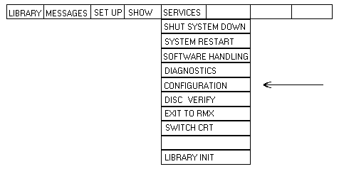
Call up the program for software configuration by selecting Services from the Utility strip at the top of the screen.
The drop-down services menu will be displayed. Select Configuration from this menu.
Services
Menu:
Configure the system by filling in a series of forms. The form heading is displayed at the top left-hand corner of each screen. The soft keys along the bottom of the forms are used to access additional forms or to access system utilities.
In this procedure we will enter information under SciNet and then Logical Names.
Use "Save & Exit" to save the parameters that you have entered, or use "Quit" to exit the configurations program without making changes.
Fields that contain a tilde (~) toggle with each press of the cursor or space bar.
The
System Configuration Screen:
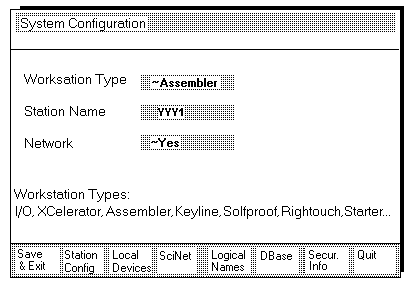
NOTE: This screen is also called "Main Menu" when selected from other screens.
At the center of the System Configuration screen find three fields:
| Workstation Type | Scroll through the selections to display the workstation type (one of those listed on the screen). |
| Station Name | Enter the station name. |
| Network | To configure your station on a LAN, toggle this field to display "Yes". |
NOTE: If you changed from Network: "NO" and your station is also on a SCSI cluster, your station and all the other stations on the cluster must be reconfigured and given an subnet name.
Accessing the Network Configuration Screen
Begin by selecting SciNet from the bottom of the System Configuration screen.
The Network Configuration screen is displayed as shown below. We can configure an SCSI, LAN or telecommunications subnetwork by selecting an option from the bottom of this screen.
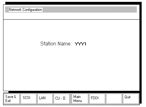
To configure a Local Area Network select LAN from the Network Configuration screen.
Defining the Stations in the Subnetwork
The Subnetwork Configuration screen is displayed. Here we inform our system of the other systems in the subnet.
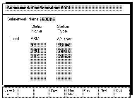
Enter information for the following fields:
| Subnetwork name | Each subnet in the network must be named. All stations on the subnetwork must use the same subnet name. |
| Station name | Enter the remote station name and toggle to display |
| Station type | the type of station (Whisper, Fyrox, or Star). |
A maximum of 8 stations can be entered on each screen. Use the Next and Prev keys to page to the next screen of 8 stations.
Exit the Subnetwork Configuration screen by selecting one of the following:
| Enter | Save your information to the system memory and return to the Network Configuration screen. You would use this to reconfigure your SCSI cluster, if necessary. |
| Main Menu | Save your information to the system memory and return to the System Configuration screen to configure the logical names. |
Logical names are a convenient way of referring to a specific station/disk combination. Rather than requiring the operator to specify the remote station, subnetwork and disk name for each transfer, a simple name is used. When communicating, the remote device is always referred to by its logical name.
In the following screen we list all the stations and disks in the communication network that we can access, and we assign them logical names. All of the station/disks that will be accessed on the entire network must be assigned logical names.
Select Logical Names from the System Configuration screen. The Logical Names Assignment Screen is displayed.
Select Remote LogNames from the bottom of the screen to display the Remote Logical Names Screen.
Remote
Logical Names Screen:
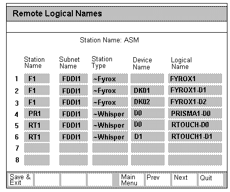
All of the station/device combinations to be accessed by this station must be entered on this screen. Use the Next and Prev keys to page to the next screen. You may enter up to 8 stations in each screen.
NOTE: If your station has already been configured on another subnet, the logical names for the stations in that subnet are also displayed on this screen.
If your station is also part of a SCSI cluster which did not have a subnet name, all the stations in the cluster must be reconfigured with a subnet name.
Enter information as follows for each system to be accessed:
| Station Name / Subnet Name | Enter
the station name and the subnet name. All
stations on a subnet must enter the same subnet
name. Do not enter your own station. |
| Station Type | Toggle to display the station type (Whisper, Fyrox, or Star). |
| Device Name | Enter the disk to be accessed. If a device name is not entered for a Response-300 station, the remote system itself will allocate the disk by priority. |
| Logical Name | Enter a logical name for each station/disk combination. |
Press Save & Exit to save both the subnet configuration and the logical names to your system disk. Restart the system and then test communications.
Restart the system as follows:
When the Response application is called up, the system is ready for communications testing.
The LANC (Local Area Network Controller) Board can be tested either from the Whisper on-line test program or through a stand-alone test that is independent of the host. The LANC on-line test is performed through the diagnostic Handler.
Getting Started
Test the LANC Board through the diagnostic handler.
The LANC is tested under INTERFACE diagnostics. Select Interfaces from the main menu, then Commun and LANC to test the board.
The LANC Diagnostic Tests
| Verify | Verify that the LANC Board is installed properly. |
| Ethernet | Display
the Ethernet address. If LANC subnet is address
configured, the address is the one that is used
in communications based on the station name, as
shown in the hexadecimal notation below: 0000 0000 0057 00XX 00XX 00XX The first three groups of four characters represent the code for Scitex systems. The second three groups of four characters express the identification number of the board. The two leading zeros of each group are not part of the 48 bit address. They should be ignored. If LANC subnet is not configured, the address is the identification number on the on-board PROM. |
| CPU | A self test is performed on the LANC CPU. |
| Memories | The
following LANC memories are tested:
A read/write operation is performed to the entire memory using the following data patterns:
|
| Peripherals | In
this test both the LANC counters and interrupts
are tested. The counters tested are:
The following interrupts are tested:
|
| DMA | The
following DMA functions are tested:
|
| Network | Before
this test the user is asked if Ethernet or Thin
Ethernet is connected and then the following
tests take place:
NOTES:
Test 1 verifies the integrity of the 82586, the Ethernet/Thin Ethernet controller. Loopback testing is performed to three points. The internal loop (1) tests the system to the 82586. The serial I/O (2) test loops back to the 82501 (the Ethernet serial I/O component). The external test (3) loops back through the network. The Time Domain Reflectometer (TDR) measures the approximate distance from the LANC to a cable failure. The distance is given in meters. |
| Eprom | A checksum is calculated for the EPROM and compared to the expected checksum. |
The stand-alone diagnostic tests enable you to test the LANC Board independently. These tests are generally used in production, when tracing board failures.
The Hardware Configuration
An RS-232 cable must be connected between the 25-pin J1 connector on the LANC Board and the terminal. The terminal must be in ANSI mode.
Program Conventions
Select a test from the menu by entering the test number on the terminal keyboard.
A test may be
performed repeatedly.
Specify the number of times that the test is to
be repeated at the display of the message
number of loops [1]
If a number is not entered the test will be
executed once.
Press
<ESC> to stop a test in progress. The
following message will be displayed on the screen
while the test is running:
PRESS <ESC> TO STOP !!!
The LANC Board Stand-Alone Test Program
Invoking the Test Program:
At power-up an automatic selftest is performed. The Main Diagnostic test menu, shown below, is displayed on the screen.
The automatic selftest consists of
the complete test series (items 1 through 6). A PASS/FAIL
message is displayed adjacent to each test.
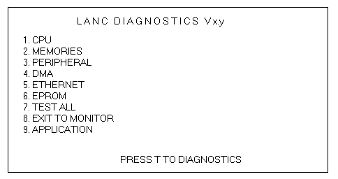
Press "T" during the selftest to remain in diagnostic mode.
Items 1 through 6 in the above menu are the elements of the LANC that can
be tested. Items 7 through 9 are the utilities.
The Diagnostic Tests
CPU (1)
Test the CPU.
MEMORIES (2)
The system enables you to test 4
different LANC memories. Select one of the memories from
the following menu.

DOWN LOAD RAM, T/R BUF,
and DYNAMIC RAM:
These memories are tested by writing a specific pattern
to the memory, reading it back, and comparing the
received and expected values.
The memory may be tested using one of 4 data patterns
displayed in the following menu:

Enter a number 1 through 3 to
select one of the data patterns or select 7 to test the
memory using all of the patterns.
NOTE: Address
(option 2) is the default option.
rotate data pattern
Each bit of the memory is tested using a pattern of rotating 1's.
address data pattern
Data equal to the value of the data address is loaded to the memory.
chess data pattern
Data in an alternating pattern of 1's and 0's is loaded to memory.
const data pattern
A single data value is loaded to the entire memory. The constant must be supplied by the user.
method: all
The memory is tested using all of the patterns above.
If the test fails, the error will be displayed in the following format:
MEMORIES: FAIL base address offset address read data write data
ETHERNET NODE ADDRESS
This option enables you to identify
the LANC Board by reading its identification number from
the on-board PROM. The following hexadecimal notation is
used for the node address:

The first three groups of four characters represent the code for Scitex systems. The second three groups of four characters express the identification number of the board.
NOTE:
PERIPHERALS (3)
Two CPU peripherals can be tested:

Select COUNTERS (1) to test the
following:

Select INTERRUPTS (2) to test the
following:

If the test fails the error will be displayed in the following format:
PERIPHERAL: FAIL type of failure
DMA (4)
Select an option from the following
menu to test different functions of the DMA.

If the test fails the error is displayed in the following format:
DMA: FAIL DMA function failure
The failure can be:
ETHERNET (5)
Select an option from the following
menu to test different aspects of the Ethernet
communication.

82586 DIAG
Test the Ethernet controller component.
If the test fails, the error will be displayed in the following format:
ETHERNET: FAIL 82586 DIAG DIAG ERR
Loopback
Select an option from the following
menu to perform loopback testing from three points on the
communication link.

If the test fails the error will be displayed in the following format:
ETHERNET: FAIL LOOP BACK loopback type error type
The error type is:
T.D.R.
The Time Domain Reflectometer (TDR) measures the distance from the LANC to the cable fault.
If the test fails the error will be displayed in the following format:
ETHERNET: FAIL T.D.R. error type
where error type is:
EPROM (6)
In option 6 a checksum is calculated for the on-board EPROM. The actual and calculated checksums are compared.
If the test fails, the error will be displayed in the following format:
EPROM: FAIL calculated checksum
The Test Utilities
Options 7, 8 and 9 in the Main Diagnostic test menu are the diagnostic utilities.
| 7 TEST ALL | perform all six tests in a batch |
| 8 EXIT TO MONITOR | exit to monitor mode for debugging |
| 9 APPLICATION | exit to the application program |