Overview
When using both the PS2 and the Brisque with the plotter, calibration of the
plotter should be done with the Brisque. Calibration settings should be applicable for
both hosts.
Before beginning the calibration only default values should
be entered in the different fields.
There are three general procedures of calibration.
Exposable Area Calibration
Punch Calibration
Align to punch in the Brisque as opposed to the PS2
Create a full format synthetic file (812 mm H by 1117 mm W)
with the ‘CreateFile’ application.
Check that the entire image is exposed.
If the image width is less then 1117 mm, calibrate the following
parameters
Reduce home margin width, end Margin width to 15 mm or
less if necessary.
Decrease the Roller parameter (plotter setting) so the
roller will be at the edge of the film and will not interfere with the laser beam.
If the size of the film is less then 1188 mm when exposing
full size 812 mm X 1117 mm, reduce the feeder offset parameter (plotter setting) to
increase the width of the film (exposing direction).
The Feeder value The Feeder value is calibrated by loading a requested film length to the plotter.
[Util screen, Film, Load Media]. If the plotter did not load the requested length
add/subtract the difference to the Feeder value in the Plotter Setting dialog.
Example: If 500 mm of film was requested, and the loaded film
is measured as 508 mm, add 8 mm to the Feeder value (50 mm default) and insert 58 mm as
the Feeder value.
The Roller value The Roller value is calibrated with the plotter’s side cover removed. When
the plotter loads film into the drum the roller should be 5 mm from the film end. Use a
piece of paper to measure the actual distance of the roller from the film’s end. The
difference should be added/subtracted to the Roller value in the Plotter Setting dialog.
Example: If 8 mm is measured from the roller to the film end,
subtract 3 mm from 60 mm (Roller default value) and insert 57 mm as the Roller value.
To calibrate the
Film Start value Expose a calibration file (LW file named ’OFFSET’, with horizontal and
vertical rulers which starts from the beginning of the file) from the Brisque to the
plotter’s small cassette. If the calibration file is covered in the H direction or is
not 5-7 mm from the film edge, measure the distance of the file from its proper position
and add/subtract it to the Film Start field.
To calibrate the
Film End value Repeat the previous step for the medium or large cassette, and update accordingly
the Film End field.
Expose a full
format file (812mm * 1117mm) from the Brisque to the plotter
Check the film for complete exposure (check that the file is exposed
812 mm * 1117 mm).
If the file is covered in the W direction, add (if covered at the beginning
of the file) or subtract (if covered at the end)
to the W Expose Offset (Enc. ck) field.
If in the W direction the beginning of the file is not 20-30
mm from the film edge, add/subtract to the large cassette W home margin.
If in the W direction the end of the file is not 30-40 mm from
the film edge, add/subtract to the lower cassette and the W end margin.
If the file is covered in the H direction add/subtract to the
H home and end margins.
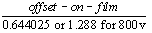
If the Brisque provides a message "Layout is too big
...", check the following:
- Check that (up to Micro - version 5.16):
- Check that the (large cassette home margin + cassette end
margin) < Media Width - 812.
If these two conditions are not met, subtract from the W or H home/end margins.
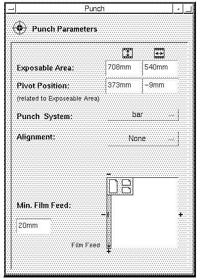
If a punch system is installed in the plotter, check in the
Brisque that the exposable area field [punch subdialog in the expose dialog] shows 812 mm
* 1117 mm. If not, check step 5 again. Punch window
If 1- 5 are not reconcilable, then increase the Max Film Feed
and repeat the entire calibration procedure.
Expose the file again and check for the file’s
calibration.
Punch Calibration
The calibration of the punch system should be done only after the exposible
area is calibrated.
After installing the punch system, expose a full format file
with punch requested, without alignment to punch (AutoArrange or Single with
alignment ‘none’). Punch window
Check that the file is still exposed entirely after the punch
system is installed. If not, repeat exposable area calibration.
Check that the central punch hole is exactly at the position
across the center of the file. If not, calibrate the punch central hole.
Only after the central hole of the punch system is calibrated
to the full format center, continue with the rest of the punch-system’s
calibration. After calibration is complete, check again exposure of a full format file and
the location of its center in relation to the punch system.
When calibrating the punch pivot to 820 H x 558 W mm, we need
to check that the full size format can be exposed on film as described before. In order to
activate the punch setting in the Brisque station, install first the center punch unit.
There is no need to adjust this punch mechanically to the punch pivot parameters at this
point.
Start the punch pivot calibration by setting the punch pivot to 820 H
(Center Height), 558 W (Center Width) [NVM screen, Cri, Service Tables, Punch
Settings]. Drag a full format file on an expose template, request bottom-center alignment
to the punch with a -10,0 mm offset from pivot [job ticket launcher, expose dialog, punch
subdialog].
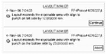
If the Brisque announces that the file exceeds the exposable
area on the left side, add to the punch pivot (punch setting) in the width direction
according to the message.
If the Brisque announces that the file exceeds the exposable
area on the right side, subtract from the punch pivot width direction according to the
message.
If the Brisque announces that the file exceeds the exposable
area on the top side, subtract from the punch pivot height parameter.
The parameter in the punch dialog (Brisque station)
“width offset “should stay “0”.
All necessary adjustments in the width direction (exposing direction) should be
adjusted via the punch pivot in the punch setting (Dolev 800). This is the safest way,
thus when the customer uses different templates, the image will continue to stay in the
center.
Initiate the ‘plotter configuration’ dialog, press
the ‘punch’ button in the dialog and check that the punch pivot is identical to
the pivot value entered in the plotter.
Check again that the punch central hole is exactly at the
requested offset from the file’s bottom center. If not, adjust the punch pivot
setting accordingly. Repeat exposure after initiating the ‘plotter
configuration’dialog and check offset again.
It is crucial that the center punch hole matches the punch
pivot parameter, so that the image will be centered to the center hole.
If you follow this process from the beginning, you should have
by now a full size image 1117 mm x 820 mm with the punch pivot parameter BC selected
without any error massages. Now you can continue with the punch installation.
Adjust the (round) center punch unit so the hole is
centered to the image in the width direction (1188 mm / 2 = 594 mm).
In the Brisque: The pivot is at 817 H, 558.5 W (relative to
exposable area). The alignment that was requested was (-25) H, 0 W, Bottom-Center.
In the PS2: To get the same alignment, insert in the requested
Punch format the (Punch pivot + Offset) at the requested alignment field.
Insert 817 + (-25)=792 at the ‘Bottom’ field and 558.5 + 0 = 558.5 at the
‘Center’ field. Request Bottom-Center alignment.
After calibration the PS2 and the Brisque should produce the
same result.