Home | Contact Us | Submit Troubleshooting Info | Search | Help
Output | Software Solutions | Proofing | Color, Screening and Calibration | Scanning | Digital Photography | Consumables | POS
Home | Contact Us | Submit Troubleshooting Info | Search | Help
Output | Software Solutions | Proofing | Color, Screening and Calibration | Scanning | Digital Photography | Consumables | POS
Connecting an Imagesetter Using the VLSI/SFL Boards
Installation of the SFL board requires the following:
To install the SFL board:
 |
Before installing the SFL board, attach the connecting bracket to the component side of the board. |
Verifying VLSI Dip Switch Settings
For the VLSI Class II board (Cat# 503D40259), the dip switches should be set as follows:
Installed in Imagesetter U311 On: 4, 5, 6, 8 Off: 1, 2, 3, 7
U314 On: 2, 3, 4, 5, 6, 7, 8 Off: 1
Dip Switches with no change U1515
(4 switch)On: 2 Off: 1, 3, 4
U1308A
(4 switch)On: 1 Off: 2, 3, 4
For VSLI Class Board (Cat# 503D38691) the dip switches should be set as follows:
Installed in Imagesetter U906 On: 2, 3, 4, 5, 6, 7, 8 Off: 1,
U311 On: 4, 6, 7 Off: 1, 2, 3, 5, 8
U1403 On: none Off: 1, 2, 3, 4, 5, 6, 7, 8
Connecting the VLSI Board to the SFL Board
A fiber optic cable is used to connect the VLSI board (located inside the Imagesetter) to the SFL board (located inside the Brisque).
To connect the VLSI board to the SFL board:
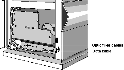
Connecting the Fiber Optic Cable to the VLSI Board
 |
IMPORTANT: Do not proceed further than the Console login before connecting the fiber optic cable. |
|
When the Brisque is powered on, one connector on the SFL board emits a fine red light. |
- First, connect the fiber optic cable plug that does not emit any light to the connector on the SFL board that does emit a fine red light.
- Second, connect the fiber optic cable plug that does emit light to the connector on the SFL board that does not emit a fine red light.
Verifying the Imagesetter Connection
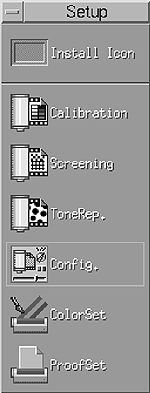
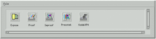
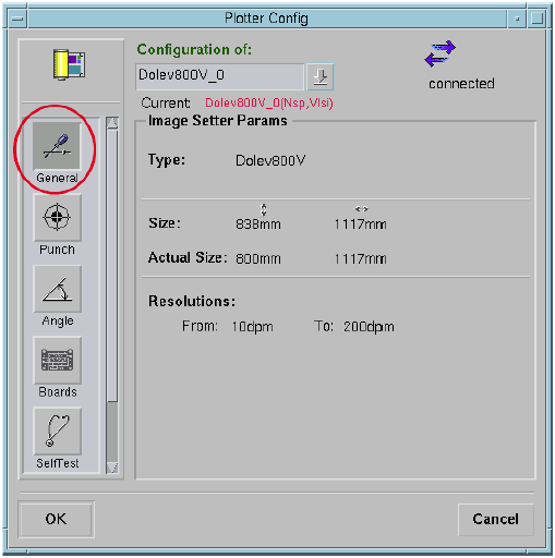
To verify the imagesetter connection: