Home | Contact Us | Submit Troubleshooting Info | Search | Help
Output | Software Solutions | Proofing | Color, Screening and Calibration | Scanning | Digital Photography | Consumables | POS
Home | Contact Us | Submit Troubleshooting Info | Search | Help
Output | Software Solutions | Proofing | Color, Screening and Calibration | Scanning | Digital Photography | Consumables | POS
Installing an Imagesetter (E30)
Connecting an Imagesetter
Verifying VLSI Dip Switch
Settings
Imagesetter Installation
Verification
Connecting an Imagesetter
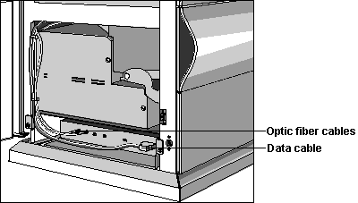
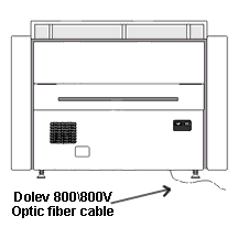
Connection to an Imagesetter is through a fiber optic cable and the SFL card on the Brisque.
Figure 1-11a. Connecting Fiber Optic Cable to
Dolev 4press
Figure 1-11b. Fiber Optic Cable in
Dolev 800\800V
Verifying VLSI Dip Switch Settings
 |
For the VLSI Class II board (Cat# 503D40259), the dip switches should be set as follows: |
Installed in Imagesetter U311 On: 4, 5, 6, 8 Off: 1, 2, 3, 7
U314 On: 2, 3, 4, 5, 6, 7, 8 Off: 1
Dip Switches with no change U1515
(4 switch)On: 2 Off: 1, 3, 4
U1308A
(4 switch)On: 1 Off: 2, 3, 4
|
For VSLI Class Board (Cat# 503D38691) the dip switches should be set as follows: |
Installed in Imagesetter U906 On: 2, 3, 4, 5, 6, 7, 8 Off: 1,
U311 On: 4, 6, 7 Off: 1, 2, 3, 5, 8
U1403 On: none Off: 1, 2, 3, 4, 5, 6, 7, 8
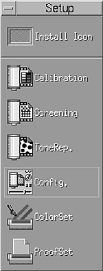
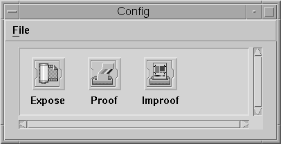
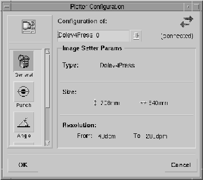
The Plotter Configuration window displays (connected) in the top right-hand corner if the installation is successful, and the name of the Imagesetter is displayed in the middle of the window.
Copyright (c)1998 Scitex Corporation Ltd. All rights reserved. Certain names, logos, designs, titles, words or phrases on this page may constitute trademarks, servicemarks, or tradenames of CreoScitex Corporation Ltd. or other entities which may be registered in certain jurisdictions.